48V solar charge controller

Thread Starter

DJS

Joined Sep 13, 2019
30
Hello everyone,
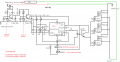
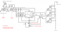
The attached circuit is a 48VDC (50 Ampere) solar charge controller.We have been using this circuit (attached) at many sites to charging 48V batteries. The circuit is designed to work as follows.

1) This is a simple ON/OFF charger (No PWM)
2) start charging if battery voltage is below 52V
3) cut off the charging at approx. 55V (maintaining hysterisis)

The problem we are facing are:

1) At some odd instances, the gate voltage becomes abnormal resulting in FET (IRFB4321) being neither turn OFF completely nor fully turned ON and FET are seen burnt.

2) Once the FET are burnt the circuit would no longer controls the charging.

Suggestions for solving this issue would be appreciated.

DJS
 

Attachments

Thread Starter

DJS

Joined Sep 13, 2019
30
Hi Eric,
Yes, that how the complete charge controller wiring would be. Please let me know if you need additional info.
Best,
DJS
 

Thread Starter

DJS

Joined Sep 13, 2019
30
Hi Eric,
while our discussion is on, i would like to know what additional circuit will be needed to ensure that charging stops if the MOSFETs are shorted. This is one of the biggest problem seen in my circuit. I have seen good solar controller like 'MORNINGSTAR' where in it has some kind of protection system which stops the charging if MOSFET gets shorted. I was just wondering how such protection is done. Kindly enlighten me about that too. Thank you.

Best,
DJS
 

TeeKay6

Joined Apr 20, 2019
573
Dear Eric,
The .asc file of the correct circuit diagram is attached. But simulator is not showing the result.

Best,
DJS
@DJS
Regarding your MOSFET heating... I believe the problem is that your LTspice schematic does not show the inherent substrate diode of the MOSFET (cathode to drain, anode to source), even though the Spice model clearly incorporates that diode. In the attached simulation I have increased the range of solar panel output to 30-55V (green). Also shown is Vgs (gray) and Id (orange). Note the very high current flow through the invisible diode as long as the solar panel voltage is less than the battery voltage. That high current is limited only by what the components shown can provide: battery=infinite current, panel=infinite current, MOSFET=according to type and Vgs and Ron. Of course, real currents will be less than shown, but still could be high.
View attachment 186277
 
Last edited:

Thread Starter

DJS

Joined Sep 13, 2019
30
Dear Eric,
Thank you for pointing out the possible causes of the problem. I am also reviewing my circuit based on your suggestion. I will update if i have any update.
The next important issue is how to stop charging when the MOSFET gets shorted. Do we need to add some kind of protection circuit? Please suggest.

Best ,
DJS
 

ericgibbs

Joined Jan 29, 2010
18,766
hi DJS,
Been looking over the post #8 circuit, tried a simplified version, I cannot see how we can get charge on at <=52V and charge off at => 56V with this circuit using a 555.
Obviously you want to to switch the charge back on when Vbat falls to 52V.

I would recommend you consider using a Comparator circuit, say a dual LM393 , as a window comparator, instead of the 555.

E
 

Thread Starter

DJS

Joined Sep 13, 2019
30
hi DJS,
Been looking over the post #8 circuit, tried a simplified version, I cannot see how we can get charge on at <=52V and charge off at => 56V with this circuit using a 555.
Obviously you want to to switch the charge back on when Vbat falls to 52V.

I would recommend you consider using a Comparator circuit, say a dual LM393 , as a window comparator, instead of the 555.

E
Hi Eric,

This circuit actually is working in many places and have not seen other problems except the cases of MOSFET burn, shorted in few instances. I tried simulation of circuit considering two separate cases. One case to see the output of NE555 pin 3 when battery voltage rises from 47V to 57V. And second case for battery voltage falling from 57V to 47V. Simulation looks perfect and it is showing that NE555 Pin 3 is LOW and then HIGH respectively for two cases. Please refer to attachment.

The only problem as i mentioned in my previous thread are 1) MOSFET are found burnt or shorted in certain cases 2) MOSFET keeps charging the battery once it is shorted as it acts like direct connection to battery from solar panels.

Best,
DJS
 

Attachments

ericgibbs

Joined Jan 29, 2010
18,766
hi DJS,
To be sure that my system was not acting up, I re-ran the sims.
Note with a real diode you should allow at least a 0.7V drop across the diode, this will effect the sense resistor values as shown.

Now I have a reasonable sim I can check out the 'hot' MOSET' problem.

E
 

Attachments

Thread Starter

DJS

Joined Sep 13, 2019
30
Hi Eric,

I am sharing you a solar controller diagram found while Googling. The circuit has two MOSFETs connected in series back to back which looks similar to one i have seen in MorningStar controllers. May be this how MorningStar stops the charging when one of MOSFET in series gets shorted. Hope this circuit will shed some lights on us in designing protection circuit that i have been looking for long time.

Best,
DJS
 

Attachments

Thread Starter

DJS

Joined Sep 13, 2019
30
Hi Eric,
I am not able to understand this sim image. May i request you to elaborate the problem in detail? Thanks.

Regards,
DJS
 

ericgibbs

Joined Jan 29, 2010
18,766
hi,
At the switching point any small change in Vbat or Solar voltages causes the threshold voltages to change.
Usually the circuit has hysteresis at the switching point which changes the threshold in order to prevent oscillation.
If the drive to the MOSFET Gate switches at a very rate the MOSFET will get hot.

As you can see on that last sim the switching signal is oscillating and the sim locks up.
E

EDIT:
In the SCC circuit this circuit the 1meg in the comparator supplies the positive hysteresis.
 

Attachments

Last edited:

Thread Starter

DJS

Joined Sep 13, 2019
30
Hi Eric,

Thank you for finding out the problem. The circuit indeed was designed to have hysteresis of approximately 2v-3v so that it does not start charging again until the voltage drops to around 52v. It was done this way to avoid oscillation in case of small voltage change in battery. But it seems, oscillation still exists. Kindly suggest how this issue can be solved.

Best,
DJS
 
Top