48V/50A solar charge controller using LT3763

Thread Starter

DJS

Joined Sep 13, 2019
30
Hello everyone,
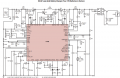
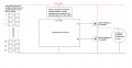
I am trying to build a Solar charge controller circuit for charging 48V battery at maximum of 50A. I have found one circuit diagram (LTspice simulation file attached) from web that could be good starting point for me to proceed. This circuit is designed for charging 12V battery. So i need some kind of guidance as to what changes would be required to make this circuit to work as a 48V solar charge controller.

Any feedback would be appreciated.
Best,
DJS
 

Attachments

ericgibbs

Joined Jan 29, 2010
18,766
hi DJS,
Which type of MOSFET are you planning to use for the controller.?
Will the 55Vout limit of the LT3763 be high enough to charge the 48V battery pack to its rated capacity.?

E

BTW: What is the specification of the Solar Panel V/A.?
 
Last edited:

Alec_t

Joined Sep 17, 2013
14,280
If your 48V battery pack is four 12V batteries in series, that circuit can't ensure balanced charging of the batteries. IMO it would be better to charge the batteries individually.
If you were to charge four 12V lead-acid batteries in series the charger would need to provide at least 4 x 14V = 56V. That exceeds the rating of the LT3763. Your requirement for a 50A charge current also exceeds the 20A limit of the IC.
To make full use of available sunshine, are you planning to have a buck-boost regulator between the panel output and the charger?
 
Last edited:

Thread Starter

DJS

Joined Sep 13, 2019
30
Hi Alec and Eric,
To answer your questions, i have drawn a concept diagram of the controller. This is just a concept and needs addition of components to work as expected. My target is to make the originally posted LT3763 circuit this way for charging 48V battery. Kindly look at it and guide me how it can be done. Thank you in advance.

Best,
DJS
 

Attachments

ericgibbs

Joined Jan 29, 2010
18,766
hi DJS,
Looking at the basic set up for LT3763, this sim shows how the controller should perform.

The circled parts of the LT circuit when using a reduced 80V down to 60V could be a problem area.
The larger circle shows the input current limit sense resistor, at first checking it suggests that the 80V > 60V may have to be capable of passing the full 50A.???

E

Footnote: This LT3763 would not be my first choice for a 5Kwatt, Solar > Battery controller, its too darned fussy.;)
 

Attachments

Last edited:

Alec_t

Joined Sep 17, 2013
14,280
I don't see using resistors to drop the voltage down from ~80V to <60V being feasible. If a resistor is chosen to pass 50A, then as soon as the charging current reduces, for whatever reason, the voltage on the IC will go above 60V and fry the IC. Methinks you need a buck-boost converter between panel and charger.
There's also the problem that to charge a nominal 48V battery pack fully will require a charging voltage above (or very close to) the maximum rating (55V) of the LT3763. It's never a good idea to operate any component at or very close to its limits.
 

Thread Starter

DJS

Joined Sep 13, 2019
30
Hi,
The sim output looks perfect. Regarding Vin voltage for LT3763 i have different idea. I will add a resistor not in the path where heavy charging current flows, Instead it shall be added right in front of Vin PIN of LT3763 just to reduce supply voltage for LT. Please refer to diagram attached. I think, this way it should not be problem for LT if voltage can be brought down to 40-50V. BTW LT3763 operates between 6V - 60V.

Apart from input voltage to LT, is there any other consideration that i should think of?
Thank you for feedback and advise.
Best,
DJS
 

Attachments

Alec_t

Joined Sep 17, 2013
14,280
Your proposed placement of the resistor would still leave pins 6 and 7 exposed to excessive voltage.
BTW LT3763 operates between 6V - 60V.
That's the input rating. What about the 55V rated maximum for the output voltage?
 

Thread Starter

DJS

Joined Sep 13, 2019
30
Alec_t is right that because of output voltage limitation (max 55V), probably LT 3763 is no suitable for 48V battery charging. So i am dropping this idea.

Instead there is a option of using LT8490 which has wider input and output voltage range (upto 80V). The datasheet also has complete circuit diagram for solar charging of 56V battery (essentially it is for 48V battery, diagram attached). But the circuit is very complex with hundreds of external components. I am wondering if that circuit can be simplified as i will not need following features.
1. Temperature compensation not required.
2. Input current control not required
3. Timer limit not required

Best,
DJS
 

Attachments

Alec_t

Joined Sep 17, 2013
14,280
The LT8490 looks good for your application. Good luck finding a Spice model for it.
1. Temperature compensation not required.
2. Input current control not required
I would have thought both those features would be necessary to prevent cell damage?
 
Top