4047 vs 555 output waveforms

Thread Starter

Hextejas

Joined Sep 29, 2017
187
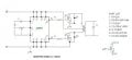
I have been going about this a lot of different ways. I was trying to convert a low voltage DC to AC without an xformer. Y`all convinced me to get a wall wort (wart?) Which I did. Of course I think that I finally got a circuit to work. It is this one minus the xformer and transistors. The RC combo yields 60Hz from pin 10. Which I then hopefully ran through an LC combo of
470 uh and 1 uf. Amazingly it produced 60Hz and even more remarkably, it read 4.25v on my AC meter
IC-4047-inverter-circuit-1.jpg
Then on to the 555 attempt and I dont know why it is not generating AC. The RC combo puts out a frequency of 82Hz at pin 3. Would there be a difference between the 2 waveforms so as to prevent it from working like the 4047 does ?
I don't have a scope yet so I can't take a peek.
Sine-wave-generator-circuit-with-a-555-timer.png
 

Attachments

MrChips

Joined Oct 2, 2009
30,806
If you would like to experiment with a 555-timer in a voltage multiplier circuit, you can try the following for starters:


AlbertHall

Joined Jun 4, 2014
12,346
470uH and 1uF are resonant at about 7kHz so they are not going to convert an 82Hz square wave into a sine wave. All you'll get is a little ringing on the edges of the square wave.
 

Audioguru

Joined Dec 20, 2007
11,248
Your timing resistor value for the CD4047 is way too low for it to produce 60Hz with a huge 22uF timing capacitor. Texas Instruments recommend no less than 10k for the timing resistor. Mine produces 60Hz at pins 10 and 11 when the resistor is 39k and the capacitor is 100nF (0.1uF) 5% metalized plastic film.

A 555 barely works at its minimum allowed supply voltage of 4.5V. The CD4047 works fine from a supply that is from 3V to 18V.
 

Thread Starter

Hextejas

Joined Sep 29, 2017
187
I forgot to mention that I am using a depleted, 9v battery that reads at 8.5v.
Sorry for the forgetfulness .
Mr. Chips, I am grateful for your schematic and will get right on it as soon as I figure out where I went wrong with the calcs.
 

Audioguru

Joined Dec 20, 2007
11,248
I forgot to mention that I am using a depleted, 9v battery that reads at 8.5v.
The old battery makes worse the missing supply bypass capacitor that every electronic circuit needs.
Try a 100uF parallel to a 0.1uF ceramic at the power pins of the 555.
 

Thread Starter

Hextejas

Joined Sep 29, 2017
187
The old battery makes worse the missing supply bypass capacitor that every electronic circuit needs.
Try a 100uF parallel to a 0.1uF ceramic at the power pins of the 555.
Guru, I see your recommendation, or something similar, quite a lot. Would you do this or something similar to every circuit ?
Probably not as "every" is way too broad. Can you recommend some general reading that talks about when to do it and why ?

As an aside I started building Mr. Chips circuit and it was so frustrating. I built it and tore it down 5 times, just the 555 portion. Turns out the breadboard as well as some wires were faulty. I nearly gave up but it's working now.
I don't have any 1n4008 laying around so am gonna try a substitute that I found. Now watch my smoke.

Thanks.
 

Thread Starter

Hextejas

Joined Sep 29, 2017
187
Did it, and now a few questions and a report.
Voltage source is 9v. Is that VCC?
I used 1N4000 since I had them

Frequency and voltage at pin 3 are :
1) 3.04 kHz, 4.25 DC, 3.7 AC according to my meter. Is it really AC if that makes sense or is it a pulsating DC that my meter thinks is AC.
2) My output at the end of the pin 3 chain is 17v DC. Not quite the 22 but I'll take it.
3) What is the symbol between the "O" the +22 ?
4) The arrow at the right shows +12V. Where did that come from since I started with 16.

I think I will crank it up to 16V and see what happens.
 

Audioguru

Joined Dec 20, 2007
11,248
Guru, I see your recommendation, or something similar, quite a lot. Would you do this or something similar to every circuit ?
Probably not as "every" is way too broad. Can you recommend some general reading that talks about when to do it and why ?
I don't read old books anymore.
If a power supply has some series resistance (like a battery) or series impedance (like the inductance of wires from a power supply) then the output of a circuit has currents that cause the supply voltage to jump up and down which passes along to an input stage and causes oscillation or malfunctions. A bypass capacitor at the circuit prevents these problems on EVERY circuit.
 

Thread Starter

Hextejas

Joined Sep 29, 2017
187
I don't read old books anymore.
If a power supply has some series resistance (like a battery) or series impedance (like the inductance of wires from a power supply) then the output of a circuit has currents that cause the supply voltage to jump up and down which passes along to an input stage and causes oscillation or malfunctions. A bypass capacitor at the circuit prevents these problems on EVERY circuit.
Ok, so are there some considerations as to which sizes of capacitors to use ?
 

MrChips

Joined Oct 2, 2009
30,806
Did it, and now a few questions and a report.
Voltage source is 9v. Is that VCC?
I used 1N4000 since I had them

Frequency and voltage at pin 3 are :
1) 3.04 kHz, 4.25 DC, 3.7 AC according to my meter. Is it really AC if that makes sense or is it a pulsating DC that my meter thinks is AC.
It can be confusing what is regarded as AC or AC + DC. The output signal is a square wave with low voltages at 0V and high voltages at Vcc, which is 9V in your case. You can look at this as -4.5V to +4.5V AC with a +4.5VDC offset. Some DMM will try to show RMS values which you will have to learn how to interpret.
2) My output at the end of the pin 3 chain is 17v DC. Not quite the 22 but I'll take it.
Expected output is approaching twice Vcc. 17V is close enough.
3) What is the symbol between the "O" the +22 ?
The symbol is two squiggles which means "close to" or "approximately".
4) The arrow at the right shows +12V. Where did that come from since I started with 16.
The arrow is the +ve terminal of the power supply that the author used, +12V in this case.
I think I will crank it up to 16V and see what happens.
Vcc of 16V should give close to double that or about 31VDC.
 

Audioguru

Joined Dec 20, 2007
11,248
Ok, so are there some considerations as to which sizes of capacitors to use ?
A CD4xxx operates with low currents and not at high frequencies so a 10uF electrolytic supply bypass capacitor is fine when mounted close to the power supply pins.

A 555 produces 400mA supply current spikes each time it switches so the datasheet recommends a 0.1uF (ceramic) parallel with 1uF supply bypass capacitors.
 

Thread Starter

Hextejas

Joined Sep 29, 2017
187
A CD4xxx operates with low currents and not at high frequencies so a 10uF electrolytic supply bypass capacitor is fine when mounted close to the power supply pins.

A 555 produces 400mA supply current spikes each time it switches so the datasheet recommends a 0.1uF (ceramic) parallel with 1uF supply bypass capacitors.
Interesting. And are those spikes introduced to the circuit via pin 3 ?
 

Audioguru

Joined Dec 20, 2007
11,248
Interesting. And are those spikes introduced to the circuit via pin 3 ?
The output circuit inside a 555 is old fashioned TTL push-pull transistors. When it switches, both output transistors conduct for a moment creating a 400mA current spike inside it and in its power supply, even without a load. The current spike causes the supply voltage to drop without proper supply bypass capacitors. A Cmos 555 does not produce the current spike.
 

Thread Starter

Hextejas

Joined Sep 29, 2017
187
The output circuit inside a 555 is old fashioned TTL push-pull transistors. When it switches, both output transistors conduct for a moment creating a 400mA current spike inside it and in its power supply, even without a load. The current spike causes the supply voltage to drop without proper supply bypass capacitors. A Cmos 555 does not produce the current spike.
Blink blink, I didn't know there were different devices in the 555 family (there is a lot I don't know). Now to go take a look at it and get a few.
 

Audioguru

Joined Dec 20, 2007
11,248
The Cmos 555 ICs are the LMC555, TLC555 and ICM7555. There might also be one made by ST Micro.
They work from a supply that is from 2V to 18V but 15V is the recommended max.
They have a low supply current and low output current much less than an older 555. Their output goes almost rail to rail if the load current is low.
 
Top