4017 counter signal to toggle between two PWM signals

ElectricSpidey

Joined Dec 2, 2017
3,350
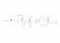
You need a resistor between output 9 and Q3 base, and it should be emitter to ground. (Q3 may just be a schematic mistake?)

For the noise…Place a diode right across the servo connections where they connect to the board. (cathode to positive!!)

Place a 100uf cap on the top power rails, and a 10uf on the bottom rails.

Put in those .1uf caps at each chip.

Ditch D10.

Why did you put D8 back in the circuit? Didn’t you have enough trouble with that…Place it on one of the other unused outputs if you really need to see the 4017 work.

As far as powering off the circuit to save the battery, you might try powering the circuit downstream from the first 555 with a MOSFET driven from the output.

As far as U1 overheating…I have no idea…sorry. Those things have a completely different internal structure I’m not familiar with.

Data sheet says you don’t need the cap on the control voltage of those 555s.

Most of your LEDs seem to be backwards in the schematic.

That’s enough for now, take care of some stuff and report back.
 
Last edited:
Thread Starter

christiannielsen

Joined Jun 30, 2019
389
I can not thank you enough.

"Put in those .1uf caps at each chip." ---> That would be a 104 ceramic right? and where should I connect it between? at the power rails too?
 

ElectricSpidey

Joined Dec 2, 2017
3,350
Yes 104, Right across the chip if possible. Should be as close to the chip as possible, at both connections. So it should span across the chip, not simply be placed at either the top or bottom rail pair.

And if you REALLY need those LEDs I would suggest using a hex Schmitt trigger buffer chip. (but, get the circuit first)
 

Thread Starter

christiannielsen

Joined Jun 30, 2019
389
Okay I am about to update my digram but here is what i've done:

104 cap placed across U1-3
100uf at top power rail
10uf at bottom power rail
D8 and D10 are removed.
Q3 is replaced correct with emitter to ground.
I put in a 5k resistor between base at Q3 and output9 at U4.
A diode is placed at power rail right beside where power to servo motor is connected.

Conclusion is that U1 is still triggered by something when signal to servo is connected.
 

ElectricSpidey

Joined Dec 2, 2017
3,350
That is a bummer, is there any way you can connect the servo to power other than at the BB?

You probably need to further de-couple the servo from the board, that could involve putting in a series resistor with the servo and placing a cap right at the servo on the other side of the resistor.

Shooting in the dark now...sorry.
 

ElectricSpidey

Joined Dec 2, 2017
3,350
No, I mean connect to the same supply, just on the other side of those alligator clips.

Unfortunately, after all of the obvious things, you have to start getting a little radical...then a lot radical.

Maybe someone with more experience using servos will help.
 

Thread Starter

christiannielsen

Joined Jun 30, 2019
389
I tried to connect a second vcc to servo motor and that helped. Unfortunately that is not the solution to use but perhaps it will help finding one.

Could it be the wrong type of diode I use?
And you said something about pulling up the trigger?
 

ElectricSpidey

Joined Dec 2, 2017
3,350
Any signal diode will do.

I see you already have R3 pulling up the trigger.

Place the servo to where the clips attach to the supply, leave the diode at the BB.

You can try placing another cap right at the sensor.

I can see the flickering of the sensor LED in the video, so the problem must be solved right at the sensor.

My gut says you have to isolate the servo from the sensor.
 

ElectricSpidey

Joined Dec 2, 2017
3,350
You can try further decoupling the sensor by placing a resistor in series with the positive rail. And placing a cap right to the sensor pins.

When you build this project will the sensor be remote or on the circuit board?

I can only assume the servo will be remote…

Always try to get as close to the finished product when doing a breadboard.
 
Last edited:

Thread Starter

christiannielsen

Joined Jun 30, 2019
389
I've tried what you described but it doesn't make any change to the U1 triggering.

I tried to pull out the sensor which didn't make any difference either.

What helped though was that I swapped the servo motor with a smaller version and now U1 is not triggering by anything but the sensor.

Could that help diagnosing?

I think a can do with the small servo motor but I have to try to install it in the santa first.
 
Last edited:

Thread Starter

christiannielsen

Joined Jun 30, 2019
389
Oh and the sensor is not suppose to be soldered to the PCB but it will naturally be very close to the PCB. The servo will be connected to the PCB with wires.
 

ElectricSpidey

Joined Dec 2, 2017
3,350
Well…

When you put the larger servo on a separate VCC and that helped, probably eliminates RFI.

Pulling out the sensor with no change tells you it’s not the sensor.

Using a smaller servo works…so that may indicate a supply droop.

Did you try connecting the larger servo power connections directly to the supply, before the wires to the board?

Have you tried the circuit with the battery, you intend to use?
 

Thread Starter

christiannielsen

Joined Jun 30, 2019
389
Well…

When you put the larger servo on a separate VCC and that helped, probably eliminates RFI.

Pulling out the sensor with no change tells you it’s not the sensor.

Using a smaller servo works…so that may indicate a supply droop.

Did you try connecting the larger servo power connections directly to the supply, before the wires to the board?

Have you tried the circuit with the battery, you intend to use?
I tried connecting power connections directly to the supply with no better result.

I just tried connecting the battery (2 cell button battery) which I was hoping would work, but It doesn't.
See this video.
 

Thread Starter

christiannielsen

Joined Jun 30, 2019
389
well it works with the small servo and that is fine. I just need to supply more power than the two cell buttons can deliver.

I am glad for your support. Thank you.

If I would like to measure how much amp this whole circuit is pulling shouldn't I be able to measure it any place on the breadboard at vcc and ground?
 
Top