4017 & 555 Police LED Lights Project (noob question)

Thread Starter

101010110

Joined Feb 19, 2015
14
Hello,

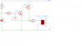
When the input of the diode is low, it will conduct and the transistor can not be switched on.
When the input of the diode is high, it is in reverse connected, and no current can flow through it, the current can go to the transistor, so the led will be on.

Bertus
well, i was close in my reasoning right? i figured out that if i have low the led will be off and if i get high the led will be on :p close enough ....
 

Thread Starter

101010110

Joined Feb 19, 2015
14
nice. thank you all for the feedback it really helped. i think i figured it out. now i`m thinking to be a little arogant and add a speaker with the sirens of a police car, any toughts on that? i presume i need to make some major changes to the project but it`ll be worth it cuz i`ll stand out from the crowd .
 

Evil Lurker

Joined Aug 25, 2011
116
The 555 provides a pulse to the CD4017. On the rising edge of each pulse the CD4017 sequentially shifts one of it's outputs high. By connecting every other output together it essentially makes it to where you have only two effective outputs, each one alternating. The purpose of the diodes on each output of the CD4017 is to keep voltage from the lone high output from back feeding into any of the other outputs that are currently low.

If you wanted to save yourself a lot of wiring on an alternating flasher just get a CD4047 IC. Essentially it functions more or less like a an astable 555 except that you can configure the outputs to where when one is active high the other will be active low.. perfect for driving MOSFETs instead of BJT transistors. The only catch with that is you wouldn't be able to modify the flash effects as you would with the CD4017, say for instance if you wanted two flashes that alternate.
 

Thread Starter

101010110

Joined Feb 19, 2015
14
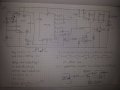
hmmm well i changed the siren circuit....i have finished my led circuit and i understood how it works...i was thinking to connect another 555 timer as a clock generator witch i will connect to a BDX53 , 93 transistor witch then will be conected to my speaker...the IN of my 2nd 555 will be the OUT of my first 555....i also tought i would use a pontetiometer betwen my first 555`s 7 pin and 8 pin, thus i can control the freq of my output witch is = to controling my led`s freq of blinking....i don`t understand why i need to capacitors next to my leds...what is the role of that? here is the shcematics for my design...the part of my siren circuit is drown separatly from the main circuit, on the bottom left of the paper, i`ve explained how i want it connected so can you please tell me what you think about that idea?
 

Attachments

Top