4 X 4 wires load cells into Wheatstone bridge configurations

Status
Not open for further replies.

ericgibbs

Joined Jan 29, 2010
21,573
hi,
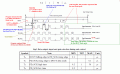
This is the timing diagram for the HX bit pattern, note the Gain is set with last set of clock pulses.
Don't forget 24 Bits can represent over 16 million in decimal, so the HX count is 'big' even for low level signals.
If you post your complete Arduino sketch and lib, I will check your settings.
for (unsigned int i = 0; i < GAIN; i++) {

E
HX711timing1.gif
 

Thread Starter

abc14

Joined Oct 15, 2017
123
hi,
This is the timing diagram for the HX bit pattern, note the Gain is set with last set of clock pulses.
Don't forget 24 Bits can represent over 16 million in decimal, so the HX count is 'big' even for low level signals.
If you post your complete Arduino sketch and lib, I will check your settings.
for (unsigned int i = 0; i < GAIN; i++) {

E
View attachment 160425
#include "HX711.h"

#define DOUT A1
#define CLK A0

HX711 scale(DOUT, CLK);

#define SERIAL_BAUD 9600
void setup() {
Serial.begin(SERIAL_BAUD);
}


unsigned long temp = 0;

void loop() {


Serial.println(scale.read());

delay(8000);

}


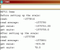
My sketch is given above, its very simple sketch just reading the raw values. Currently I have hooked up the green and white wires to channel B. B+, B-.
Link to the library is given below.

https://github.com/bogde/HX711/blob/master/HX711.cpp
 

ericgibbs

Joined Jan 29, 2010
21,573
hi,
Your program is too simple, its reading raw data. *128
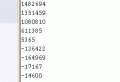
Running it on my HX711 test rig, with a trim pot on the bridge I can get these raw readings.
E
AA1 24-Sep-18 12.53.gif
 

Thread Starter

abc14

Joined Oct 15, 2017
123
hi,
Your program is too simple, its reading raw data. *128
Running it on my HX711 test rig, with a trim pot on the bridge I can get these raw readings.
E
View attachment 160426
Yes the program is simple. I actually want to make sense of raw readings and build the logic on that basis.
As I understand the gain in 128 ? Now how do you get actual voltage from 1482694, in your output.
 

ericgibbs

Joined Jan 29, 2010
21,573
I used a trim pot on a 2K bridge to generate the mV signals for the HX711.
It is not an 'actual voltage' from 1482694, its a Binary ADC value displayed in Decimal format.

Upload this file, change the extension from .txt to .ino, paste it into a new sketch, it works OK.
You can change the CAL to suit, it also uses the same Lib files.
E
 

Attachments

Thread Starter

abc14

Joined Oct 15, 2017
123
Yes the program is simple. I actually want to make sense of raw readings and build the logic on that basis.
As I understand the gain in 128 ? Now how do you get actual voltage from 1482694, in your output.

So the way to calibrate it is, lets say my raw readings are 1482694. Now if I place a known weight of 5kg and raw readings become.
I used a trim pot on a 2K bridge to generate the mV signals for the HX711.
It is not an 'actual voltage' from 1482694, its a Binary ADC value displayed in Decimal format.

Upload this file, change the extension from .txt to .ino, paste it into a new sketch, it works OK.
You can change the CAL to suit, it also uses the same Lib files.
E
I appreciate that, but what I was trying to get at, lets say my raw readings are 1482694. Now if I place a known weight of 5kg and for example raw readings have become 1482694 - 20000. It meant each 1KG would reduce my weight by 5000. Hence I would simply divide my subsequent output by 5000 and get the weight KG I am looking for ?
 

ericgibbs

Joined Jan 29, 2010
21,573
hi,
1. You have to write a program that Tares off any L/C Off Load value at power On.
2. You then have to determine the calibration factor, this is done by placing a known value weight, close to the max of the L/C say 100kg on the L/C. By changing the calibration factor you see on the serial output the actual weight.
3. Repeat until steps 2 and 3 are steady and repeatable.

If you read thru the Sketch I posted you should be able follow the required sequence.
 

Thread Starter

abc14

Joined Oct 15, 2017
123
hi,
1. You have to write a program that Tares off any L/C Off Load value at power On.
2. You then have to determine the calibration factor, this is done by placing a known value weight, close to the max of the L/C say 100kg on the L/C. By changing the calibration factor you see on the serial output the actual weight.
3. Repeat until steps 2 and 3 are steady and repeatable.


Understood. It all makes sense. One thing remains, there is no way to specify which channel we are using ? does the chip selects channel automatically ?
 

Thread Starter

abc14

Joined Oct 15, 2017
123
What do you mean by channel.?
Ain or Bin
By default the lib sets the Gain to 128 and Ain.

YEs Bin.. When I had 4 load cells connected, the channel A buffer was over flowing I was constantly getting full range 8,388,607. Then I put my Green and White wires to channel B. And I started to get readings of 267222. But Oddly enough I didn't actually specify anywhere in my sketch that I am using Bin. Instead of Ain
 

ericgibbs

Joined Jan 29, 2010
21,573
Checking the Lib,
The default is 128 Chan A.

Clip from Lib:
// set the gain factor; takes effect only after a call to read()
// channel A can be set for a 128 or 64 gain; channel B has a fixed 32 gain
// depending on the parameter, the channel is also set to either A or B
void set_gain(byte gain = 128);

void HX711::set_gain(byte gain) {
switch (gain) {
case 128: // channel A, gain factor 128
GAIN = 1;
break;
case 64: // channel A, gain factor 64
GAIN = 3;
break;
case 32: // channel B, gain factor 32
GAIN = 2;
break;
}

If you are overloading the HX711 when the L/C's are connected, then the L/C Zero Offset Diff voltage is > 15mV.

If the Vdd was 5V the max input signal at *128 is +/-20mV, using the HX711 Vext which is around 3.8V. means the max Vdiff is ~+/-15mV.

I would strongly recommend that you concentrate on debugging using just one L/C.
Using a voltmeter measure the Vdiff offset at the L/X Aout pins when Vext is the HX711. let me know what youe measure.

E

EDIT:
Modifying my test program/jig, I would say you have a negative Vdiff offset of -2.5mV [off load]
AA1 24-Sep-18 14.51.gif
 
Last edited:

MelYad

Joined Nov 10, 2023
1
I've never understood the proclivity to wire load cells in parallel, especially in regard to the complexity and time/labor involved to trim each load cell such that the combination produces an acceptable result.

My preference is to sample each load cell independently -- either using separate hi-quality ΣΔ ADCs, or one ΣΔ with multiplexed bipolar inputs -- and process the calibration of each load cell independently. The algorithm to do this is utter simplicity, simply requiring a few different weight inputs (or weight locations) and solving a trivial matrix.

This is much faster and cheaper, and each cell adjustment does not affect the other cells.
It would be super cool if you could explain this method in detail, like over a YouTube video or something.
 
Status
Not open for further replies.
Top