The boards is basically supposed to be some sort of groovebox/synthesizer. Most of it is digital with mainly buttons and RGB LEDS which are connected to the HT16k33. Onle the volume knob and 2 volumes sliders are analog. They are connected to ADC pins.
The boards is basically supposed to be some sort of groovebox/synthesizer. Most of it is digital with mainly buttons and RGB LEDS which are connected to the HT16k33. Onle the volume knob and 2 volumes sliders are analog. They are connected to ADC pins.
So the slider pots are just to send control signals to a controller board?
There are no audio or video signals on the board except for SPI or I2C signals?
The caps at RV1, RV2 and RV3 are at the wrong location. They should be at the inputs of the ADC.
Remember, every piece of wire is an antenna. The longer they are, the more EMI will be received.
Yea. the slider pots basically just send control signals. No audio signals going through.
I have another breakout board for that, but it will be separate from the whole pcb shown here.
I will probably need another smaller pcb for it.
I also tested it already and I guess in this case I would need the capacitor probably not for decoupling, more for smoothing out the signal. I tried that already in a simple setup with the raspberry pi and a breadboard, and it seemed very important )
So I wonder if I still would need a decoupling capacitor for the analog slider pots power pin?
The caps at RV1, RV2 and RV3 are at the wrong location. They should be at the inputs of the ADC.
Remember, every piece of wire is an antenna. The longer they are, the more EMI will be received.
a power connection to the Bulk Capacitor, even I have still a whole layer dedicated to power
for the volume slider I moved the capacitors closer to the pins
and for the HT16K33, even its probably not neccessary, I have also add a power connection to the decoupling capacitor and moved it closer to the power.
I hope that should all still work.
No. For the capacitors at the pots, don't move the capacitors closer to the pots. You need to move the capacitors closer to the processor board that reads the signals.
Fyi
The pots , rv1 to 3 ,are they forming a voltage source into the pi ?
What is the source of the voltage they are sourcing ,?
I'm just thinking that the capacitor as mentioned by @MrChips is aimed to remove noise.
Can you share the schematic of how the RV are used please
@MrChips : moved it closer to the processor board, thank you very much for pointing this out
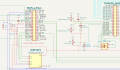
This is part of the schematic. I hope its not too messy. But the pots getting their power from the Raspberry Pi pinheader on the left. The Potentiometer are right in the middle/right. On the far right there is a another pinheader. Its comes from some sort of soundcard breakout board with ADC Pins. It doesn't send any audio signal through it though. At least not trough this pinheader.
Do you see any issues with this kind of setup?
One comment I have is the way you draw GND in the schematics.
I prefer to see GND symbols pointing towards the bottom and PWR placed higher than GND, something like this:
Fyi
The pots , rv1 to 3 ,are they forming a voltage source into the pi ?
What is the source of the voltage they are sourcing ,?
I'm just thinking that the capacitor as mentioned by @MrChips is aimed to remove noise.
Can you share the schematic of how the RV are used please
@drjohsmith : I am sorry, I would probably need your help again on this. I did some research, and it almost seems like the biggest issue is that I am mixing analog and digital signals. Also the analog signal for my 2 volume sliders goes across the whole board which probably produces a lot of noise.
Is there a good solution for that by any chance? I have already a 0.1uF capactor right next to the ADC pin, but that just smoothes out the signal. It won`t help that the analog signal trace probably acts like an antenna and interfers with all my other components?
im assuming your following Mr chips schematic ?
in which case the voltage is only varying at the speed you can move the resistors , at most a few hz ?
and this voltage is going into the pie ?
in which case , just do some filtering in the code , a simple average is probably all your code needs.
Yea, I am more concerned that the fairly long trace from the ADC pin to the actual volume pot can cause interference and noise issues to other traces or components nearby as its, an analog and not a digital signal. Or is that not really an issue?
Yea, I am more concerned that the fairly long trace from the ADC pin to the actual volume pot can cause interference and noise issues to other traces or components nearby as its, an analog and not a digital signal. Or is that not really an issue?
The EMI picked up on a long length of wire is a problem when it adds noise to the signal of your interest.
The signal on a long length of wire becomes a source of EMI if it couples on to another trace having high impedance.
In your case, the input of the ADC has high impedance. Hence it is susceptible EMI noise. The purpose of the capacitor at the input of the ADC is to reduce the EMI before it gets to the ADC. The long length of wire on the potentiometer side is not a concern because the voltage at the pot will be a steady voltage.
In fact, a long wire carrying digital signals is a worse noise generator than the analog signals on the pot.
So that you understand, all digital signals are still analog. The difference is, a digital signal usually has only two voltages and has sharp edges. It is the sharp transitions that create havoc in other sensitive signals, whether they are analog or digitally encoded.
 Facebook
 Google
 GitHub
 Linkedin


") )
)