Facebook
 Google
 GitHub
 Linkedin
Hi to all,
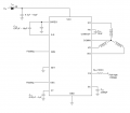
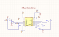
I just want to ask regarding of the 3 phase BLDC motor IC driver which I use is APX9370,
when I build the circuit it seems there's no switching happening in the 3 phase out put of the IC, its like
the output voltage of the 3 pin going to motor is constant voltage , as my study to run or to rotate the motor should the
armature winding pole should be switching the voltage of each pole, but in my circuit its not happening can some one help to
discuss the wrong in my diagram?
Attachments
-
 22.4 KB Views: 12
 -
 217.1 KB Views: 11