Facebook
 Google
 GitHub
 Linkedin
Hello, I'm new to this depth of electronics. Sorry in advance for a story. I recently purchased "The art of Electronics" and have been watching Khan Academy to help me figure out a solution to my problem and have only understood a fraction of what I've read. Please excuse my inaccurate terminology and other ignorant things I may or may not say.
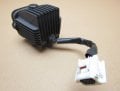
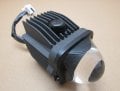
I have a vehicle that I want to swap out the poor factory headlight for one that provides a better light pattern (while looking more aesthetically pleasing) but want to keep all factory wiring intact to make swapping back easy if it doesn't work out. It so far has proven to be beyond my knowledge.
The connector at the light has:
2- key-on switched 12.6v supplies (High beam, Low beam)
2- key-on switched 12.6v supplies (running lights)
2- 35.5v inputs (from a module to turn on the low and high beams while the engine is running)
2- grounds
I originally tried using 2- 36v relays and the result was the light would flash on and off like a slow strobe light). I didn't originally check for current and the relays had no specifications on the coil other than being 36v. Probing with my multi-meter, the current at the 35.5v input from the module to ground is 17.8ma. So I'm assuming there isn't enough current to keep the coil energized?
Then the idea of using a transistor with the 35.5v at the base and the 12.6v at the collector for the relay's coil. It appears no transistor is manufactured for up to 50v (I think I saw some 30v). I didn't have much luck finding a small affordable stolid state relay either.
I'm not sure what direction to go at this point and I'm hoping I may get some assistance from here.
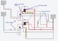
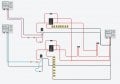
Attached is the transistor circuit I had planned on my child's tinker cad that I now don't believe will work.
I have a vehicle that I want to swap out the poor factory headlight for one that provides a better light pattern (while looking more aesthetically pleasing) but want to keep all factory wiring intact to make swapping back easy if it doesn't work out. It so far has proven to be beyond my knowledge.
The connector at the light has:
2- key-on switched 12.6v supplies (High beam, Low beam)
2- key-on switched 12.6v supplies (running lights)
2- 35.5v inputs (from a module to turn on the low and high beams while the engine is running)
2- grounds
I originally tried using 2- 36v relays and the result was the light would flash on and off like a slow strobe light). I didn't originally check for current and the relays had no specifications on the coil other than being 36v. Probing with my multi-meter, the current at the 35.5v input from the module to ground is 17.8ma. So I'm assuming there isn't enough current to keep the coil energized?
Then the idea of using a transistor with the 35.5v at the base and the 12.6v at the collector for the relay's coil. It appears no transistor is manufactured for up to 50v (I think I saw some 30v). I didn't have much luck finding a small affordable stolid state relay either.
I'm not sure what direction to go at this point and I'm hoping I may get some assistance from here.
Attached is the transistor circuit I had planned on my child's tinker cad that I now don't believe will work.
Attachments
-
 56.2 KB Views: 15