3 pin mini voltmeter connection.

Thread Starter

transforman

Joined Sep 23, 2018
35
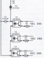
Hi to all. I have built a circuit that it can increase the voltage quite successfully, and with a 1/100 voltage divider i can actually measure the volts with a multi-meter. But i want to change the multi-meter with that small 3 wire voltmeter. Here is the circuit that i have built.


The 3 terminal mini voltmeter got 3 wires. Black is ground, yellow is voltage reading and red is Vin (5v to 12v). In order to work,i have to connect the ground both the 12v Battery and the Voltage Divider in order to get a voltage indication. What i want to ask is if there is any problem if i connect together the negative from the battery and the negative from the Voltage Divider, as you can see below.


Thanks
 

KeithWalker

Joined Jul 10, 2017
3,063
The 3 terminal mini voltmeter got 3 wires. Black is ground, yellow is voltage reading and red is Vin (5v to 12v). In order to work,i have to connect the ground both the 12v Battery and the Voltage Divider in order to get a voltage indication. What i want to ask is if there is any problem if i connect together the negative from the battery and the negative from the Voltage Divider, as you can see below.


Thanks
If you do, you will be shorting out Rdivider1.
 
Last edited:

Thread Starter

transforman

Joined Sep 23, 2018
35
Yea i am using 40 MΩ as r1 and the rest calculated to give 1/100 voltage considering vmeter resistance. KeithWalker do you have any idea how to make it work ?
 

Thread Starter

transforman

Joined Sep 23, 2018
35
Bill any idea how the photocoupler must be connected to my above circuit ? I have never use it before so i have no idea how it works.

Thanks
 

BillB3857

Joined Feb 28, 2009
2,570
Pick a DC voltage from your circuit that would power the LED of the opto and size a resistor to provide appropriate voltage/current to the LED. The battery to power the voltmeter would have one lead common to the measured voltage.
 

BillB3857

Joined Feb 28, 2009
2,570
This is a circuit I used for a custom built test fixture that used 3 meters that required full isolation from each other but would turn on/off as the equipment was turned on/off..
 

Attachments

Thread Starter

transforman

Joined Sep 23, 2018
35
Ok i understand how the opto can be used as a switch to isolate 2 circuits but in my case is voltage that have to be isolated.

Pick a DC voltage from your circuit that would power the LED of the opto and size a resistor to provide appropriate voltage/current to the LED. The battery to power the voltmeter would have one lead common to the measured voltage.
Bill the opto output where would be connected ?
 

BillB3857

Joined Feb 28, 2009
2,570
Looking at the diagram for the three meter supplies shown in my second post, each meter and its battery power supply is isolated from both the voltage supplying the opto input AND the voltages being measured. Each voltmeter becomes a stand alone meter that is turned on and off by the opto. Looking at your first post, the 12v DC source would drive the LED of the opto, the output transistor of the opto would switch the battery power to the voltmeter. The battery and voltmeter would be optically isolated from the voltage being measured and could be floating above it. I have modified your first drawing to show the opto. The value of the resistor shown would be determined based upon the specs of the opto isolator used.MeterSupply2.png
 

Thread Starter

transforman

Joined Sep 23, 2018
35
Wow Bill thank a lot mate, now i completely understood it. I really never thought about another battery only for the vmeter but it will work this way. Thanks mate, i really appreciate that.
 

BillB3857

Joined Feb 28, 2009
2,570
The digital meter modules I used were LCD type rather than LED and the battery for each meter lasted close to a year. If you have the option, go for the LCD (Liquid Crystal Display) to reduce the drain on the battery.
 
Top