3 phase rectifier using "ideal diodes"

Thread Starter

seandepagnier

Joined Nov 16, 2020
3
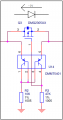
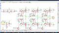
I'm building a small wind turbine and the low voltage output makes diodes, even schottky undesirable.

So I have have been exploring active rectification, however the designs seem costly. I like the raspberry pi's ideal diode circuit, however I have concern about the base-emitter breakdown voltage.

I have found https://www.mouser.com/ProductDetail/Texas-Instruments/LP395Z-NOPB which promises no damage from high voltages from base emitter, however it does not specify reverse bias breakdown and this part cost is very high.

Any suggestions for achieving active rectification for 3 phase?
 

Attachments

Thread Starter

seandepagnier

Joined Nov 16, 2020
3
Those 3 phase rectifiers do not comply with my requirement. I already wired up 6 diodes and it works, but it wastes about 10% of the power generated. It is a wonder that people accept this loss in small wind turbines and that these are still sold with such huge heat sinks, obviously wasting much energy.

I need to rectify into a 4 cell lifepo4 which is 11-14 volts but if the battery disconnects the turbin could output 30-40 volts or more. Maybe I can use an scr crowbar to prevent voltages above 20, I already have an opamp that tests this and turns on all 3 low mosfets in my design so in theory the voltage will never exceed 20 volts. The "ideal diode" circuit cannot handle voltages above 5 volts because of base emitter breakdown absolute maximum rating of 5 volts. It seems difficult to find bjt wiht higher base emitter breakdown, because I require at least 30 volts for this, and cannot find a suitable part, so I think an alternate method for syncronous rectification is needed, perhaps using opamps across each mosfet with booster to provide voltages outside the range??

How is this normally done?
 

drc_567

Joined Dec 29, 2008
1,156
... If by chance you run into any charging difficulties with your design, you could get a DC to AC inverter and use the specific lifepo4 charger/maintainer device shown here:
LiFePO4 charger/maintainer
I used a similar version for a standard gel cell battery for a while, with satisfactory results.
.. at any rate the specifications of the LiFePO4 charger may be interesting.
 
Last edited:

crutschow

Joined Mar 14, 2008
34,285
How is this normally done?
One way is to add a small diode (Schottky for minimum added forward voltage drop) in series with the base or emitter of the transistor to block any excess reverse base-emitter voltages.
That gives an extra diode-drop in the forward direction, but I don't think you will be a significant problem in your application.
 

Thread Starter

seandepagnier

Joined Nov 16, 2020
3
I don't think it will work in this particular application where the bjt is in reverse most of the time.

Using an inverter? This will waste a lot more power than I could possibly save by doing this. The turbine will output only 5-50 watts depending on wind speed..

I have found another schematic which can rectify 3 phase power using syncronous, but it's using 3 phase sine wave from mains, and what I have is pulled to trapazoidal wave form.


Now I think the solution is maybe to use a buck-boost supply to generate -2 volts (at 2ma or less) to power the negative rail of high-side amplifiers which can sense and amplify the voltage across each mosfet. These can then be inputs to comparators which then drive logic inputs to high and low style mosfet drivers to perform the active rectification. I think the quiecent current of 2ma at -2 volts is ok, especially since it's generated efficiently from 12 volts it will be microamps of quiecent current and I need a bunch of zeners to protect everything as well....
 

Ian0

Joined Aug 7, 2020
9,677
If it were single-phase it would be easy. The gate drive signals for a synchronous rectifier could easily be driven by a transformer from the generator, with an output winding for each MOSFET gate.
Three phase adds a whole extra layer of complexity! I’m assuming that your turbine is delta-wound.
Also, you are losing efficiency because current only flows at the peaks of the waveform. Look up “three phase bridgeless PFC” on your favourite search engine, that solves both diode loss and peak current losses. In your case, you can use the series inductance of the turbine as the inductor in the boost circuit.
I‘ve seen a patent for it somewhere. Maybe I’ll remember where I saw it. . . .
 

Ian0

Joined Aug 7, 2020
9,677
An alternative thought.
why not make a 24V turbine. That will halve the diode losses, and reduce the cable losses by three quarters. (Did you factor in the cable losses?). Then switched-mode Lithium battery chargers which run off 24V are plentiful.
 
Top