Could anyone assist me with something? I am trying to wire up a motor that controls lifting/lowering of a conveyor with two NC limit switches using relays. I have pictures of the relays I'm using if needed.
Show the contactors also any O/L protection. Sizing etc.
If the conveyor involves the general public or could cause danger to personnel, you may need a phase rotation detector. As used in elevators.
What initiates the conveyor?
Show the contactors also any O/L protection. Sizing etc.
If the conveyor involves the general public or could cause danger to personnel, you may need a phase rotation detector. As used in elevators.
What initiates the conveyor?
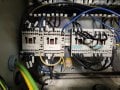
So here are the two pics I have. Relays next to power supply. The contractors for lift and lower are on bottom left. For the fwd/rev functions of the conveyor, I have to use a very small SEW drive. Ive actually never wired up a drive from scratch, but I wouldn't imagine I'd need a lot of relays for the forward and reverse motion since I have the drive.
Could anyone assist me with something? I am trying to wire up a motor that controls lifting/lowering of a conveyor with two NC limit switches using relays. I have pictures of the relays I'm using if needed.
So here are the two pics I have. Relays next to power supply. The contractors for lift and lower are on bottom left. For the fwd/rev functions of the conveyor, I have to use a very small SEW drive. Ive actually never wired up a drive from scratch, but I wouldn't imagine I'd need a lot of relays for the forward and reverse motion since I have the drive.
. The contractors for lift and lower are on bottom left. For the fwd/rev functions of the conveyor, I have to use a very small SEW drive. Ive actually never wired up a drive from scratch, but I wouldn't imagine I'd need a lot of relays for the forward and reverse motion since I have the drive.
They are Contactors, you are the Contractor!
So who has wired it up so far? and what experience do you have with Industrial installations?
I am trying to get an idea of the full 'picture'?
To come up with a DWG, the nature of the operation is needed, so far it is a little vague!
If its a vfd doesn't it have forward and reversing built in? The reversing contactors wouldn't be needed then. So like @MaxHeadRoom said we kind of need more information.
Re-reading your second post it looks like you are looking at replacing the reversing contactors with the vfd. And you're right if the drive has forward and reversing you do not need contactors for the same. From the guess of the situation you'd take the input to the vfd, the output to the motor, and remove the reversing contactors. Next would figure out the configuration of the drive and how to wire up those NC limits to the drive to let it know when to stop and how to start motion. Probably a toggle of some kind.
Again, a fuller picture of the situation is going to help. Even the old schematics would help with that.
I apologize. I should've been more thorough with my explanation.
So the two NC limit switches are to be used in conjunction with a motor that lifts/lowers the conveyor. That motor will be hard wired thru contactors. No VFD for that motor.
The second motor will be forward and reverse. No limit switches. But a VFD will be used. I thought the same thing when I looked at it when I first started. In regards to having two contactors for forward/reverse. But that's the way it was installed before. Even with a VFD. So I was just going by what was already there before.
This line is being upgraded and the majority of these components were located in a much bigger panel. Now all of this stuff has to be crammed into a box mounted on the side of the conveyor and I'm completely out of room.
If you are reversing any of the motors with contactors, they should be of the reversing kind, i.e. all in one, with electrical and mechanical interlock, also normally come with a O/L fitted to the contactor.
They are Contactors, you are the Contractor!
So who has wired it up so far? and what experience do you have with Industrial installations?
I am trying to get an idea of the full 'picture'?
To come up with a DWG, the nature of the operation is needed, so far it is a little vague!
It is rather risky if you are new to industrial installations, you will be required to conform to local code .
As a minimum, you should have a copy of the local code if in N.A. and also NFPA79 ( an PDF older copy available on line.).
There is many things to observe, from wire size and colour, to fusing and O/L sizing.
Am I wrong in guessing you are located where such regulations are lax and not enforced?
"" It is to be used as an exit conveyor for parts coming off a stamping press. ""
So, why do You need a Reverse function ?
I can understand needing a Speed-Controller,
but reversing might cause huge problems with product jams, etc..
.
.
.
The Siemens 3RH2122-1BB40 are 24VDC operated relays, the contactors should be mechanically and electrically interlocked, the ones shown are not.
A complete inventory or what is already installed and detailed explanation of the whole machine and process would be needed for any informative answer.
Pictures of the machine and detailed operation?
so very basically I think you're looking for roughly the following
I HEAVILY agree with @MaxHeadRoom that you need the reversing contactor for the up and down. The above protects electrically, but its no replacement for good old physical interlocking.
and sorry all I have at the moment is paint.
and if you're going to integrate it with that press than that a whole new set of challenges.
are you in north america? If so you'll be wanting to dive through NFAP 70 article 430 for motor protection and wire sizing. If you don't have a copy I can snippet a section of my copy (the year revision implemented by your state may be different than mine but motors haven't really had any major changes in a while). You're company should be providing you with a copy of it and the NFPA 79 for a certainty in north america.
And if you are working for a company you will have a safety department and they will be able to provide you with any relevant interlocking or safeties they require above and beyond the bare minimum in the NFPA 79.
and i know article 430 is kind of a nightmare for greenhorns to navigate so you may need some assistance in translating the legaleze from your journeyman/more senior electricain
JM has the control and limit switch connections correct in post#16, using standard IEC descriptive graphics, and I certainly appreciate THAT.
And for those concerned, I think that the forward and reverse are for the conveyor height adjusting motor. But a reverse JOG function is useful for a product conveyor when things get jammed up. But only a momentary control, no latching, hence the "JOG" term.
Incidentally in the Schneider example DWG's I posted in #2, the safety O/L contacts are shown on the wrong side of the coil, it is now considered bad practice to place them on the 'Right hand' side of the coil, they should be in the main control string.
Also: A lot more is needed than
Could anyone assist me with something? I am trying to wire up a motor that controls lifting/lowering of a conveyor with two NC limit switches using relays. I have pictures of the relays I'm using if needed.
Really, presuming the TS has the ability to design and construct an enclosure with the proper three-phase disconnect and fusing, and provide a suitable controls voltage transformer and fusing, the rest is fairly simple. And for adjusting conveyer height, probably the buttons should be fairly close to where the adjustment is done.
Also of importance is an acceptable method of implementing a typical functioning E-Stop circuit, In N.A. each Red E-Stop PB has to be mounted with a yellow background.
 Facebook
 Google
 GitHub
 Linkedin