1) How many J-Ks needed to represent 0 - 29 ?
2) Then ask yourself, what state do I have to detect to flip the counter from "last"
state to "beginning" state, and design that decoder....
What kind of counter designs have you been studying? There are a couple ways to approach a problem like this. Have you studied how to implement a binary to BCD converter?
Post your work for the decade counter and the work you've done for the 29-0 counter.
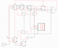
EDIT: I studied your counter circuit a bit and see that you're using the set/reset inputs on some of the flip flops. A typical counter design uses gating logic, not the set/reset inputs. The only times I've seen them used are when the counter has a set option like set to 9 or set to 0.
Somehow I don't think this is what you were asked to do. It's more typical for a student to be asked to actually design a counter, not sling gates around trying to find something that works.
Could you post the entire text of the problem and describe what you've covered in this class?
Your schematic drawing style is very difficult to read. Neatness matters a lot in schematics. Professionals never place wires over components. The schematic editor you're using introduces extraneous connection dots; you shouldn't run wires over them because it looks like a connection.
 Facebook
 Google
 GitHub
 Linkedin