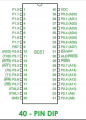
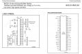
27C256DC-12 duplication and Atmel 80C32 fault finding

Thread Starter

geoffers

Joined Oct 25, 2010
520
The first 74lc573 is connected to the eprom.

The second I can't find is, both have oe connected to pin 7 of the 80c32 and there outputs to 32-39
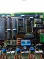
IMG_20230309_094955_700.jpg

The second one isn't connected to ale.

I wonder if the second may be connected to the 'missing' component d12
 

ericgibbs

Joined Jan 29, 2010
21,532
Morning Geoff,
Who removed D12 IC, there are solder splashes across pins, if they are shorts, I recommend you remove before further testing.

E
EG57_ 673.png

IMG_20230309_094955_700.jpg
 
Last edited:

Thread Starter

geoffers

Joined Oct 25, 2010
520
Hi Eric,

As came from factory, the other board is the same, scrapes are me getting the varnish off to see get a multimeter contact on them.

Cheers Geoff
 

MrChips

Joined Oct 2, 2009
35,020
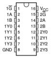
We are focusing on the D5, 74HCT573 below the two white rotary switches and the 74HCT139.

74HCT139

1678370326853.png

Trigger the oscilloscope CHAN1 on pin-1 and examine pins 2 to 7 with CHAN2
We want to know the state of each pin when pin-1 goes LOW.
 

Thread Starter

geoffers

Joined Oct 25, 2010
520
Pin 1 doesn't go low, I think the problem may be before it tries to access it's address.

I scoped pin 6 on the 80c32 which is oe for the buffer chip on data bus and that never goes low either.

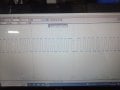
I scoped pin 6 on the good board

IMG_20230309_151250_677.jpg
This is the signal I found.

If I've understood it right pins32-39 on the 80c32 are data and address bus?

I assume they are bi directional?
And oe is sent low after the address has been sent for the data to come in from the eprom?

As oe remains high, right from power up does this suggest either a problem with the processor output pin or the buffer failed and the processor unable to pull it low?

I scoped data busses on both boards, the good one is very busy, the bad one there's not much going on, I'll post shots in a mo when I'm next to WiFi.

Cheers Geoff
 

MrChips

Joined Oct 2, 2009
35,020
80C32 pin-17 is /RW.
You show this signal pulsing.
This should be the same signal on pin-1 of 74HCT139. Is it not?
 

Thread Starter

geoffers

Joined Oct 25, 2010
520
I only have a power supply for the board on the robot (24v ac), so any readings with the oscillascope I have to do there.
So it makes sense to do a load at once so I'd done some on pins 32-39.

I accidentally added one to my reply.

Answer to your question, I haven't prodded pin 17 (80c32) with the scope, but it has good continuity to pin 1(74hct139) which is a 5v solid.

Is the rd pin used for something specific? The data sheet I have says it is on a 80c51 but doesn't say it isn't on a 80c32.

Thanks Geoff
 

MrChips

Joined Oct 2, 2009
35,020
There are three important bus control signals, ALE, /RD, and /WR.

ALE signal latches the lower byte of the 16-bit address into an 8-bit address register from the 8-bit Address/Data bus.
/RD is used to read 8-bit data via the 8-bit Address/Data bus.
/WR is used to write 8-bit data via the 8-bit Address/Data bus.

If the node address (i.e. two rotary switches) is being read via the 74HCT573 latch to the Address/Data bus, then the MCU must send out /RD active LOW.

If pin-1 of 74HCT139 is always HIGH then something is wrong.


80C32 pinout.jpg
 

Thread Starter

geoffers

Joined Oct 25, 2010
520
That makes sense,
Would I be right to assume that the 80c32 would only fetch it's address from that latch once the program is running?

If the program is held in the eprom then it must get the program from the bus (32-39) before anything else happens?

Oe on the eprom latch is also solid 5v (from pin 6 80c32) on the faulty board.

On the good board there are plenty of pulses on pin 6.

Looking at the data sheet pin 6 has a weak pull up, would that suggest it's output driver has failed?

Thanks Geoff
 

MrChips

Joined Oct 2, 2009
35,020
That makes sense,
Would I be right to assume that the 80c32 would only fetch it's address from that latch once the program is running?

If the program is held in the eprom then it must get the program from the bus (32-39) before anything else happens?

Oe on the eprom latch is also solid 5v (from pin 6 80c32) on the faulty board.

On the good board there are plenty of pulses on pin 6.

Looking at the data sheet pin 6 has a weak pull up, would that suggest it's output driver has failed?

Thanks Geoff
We don't know what goes on in the program. We can only make some tests and try to get some symptoms of what is happening.

With the working board, are you allowed to change the node address on the fly while the power is ON?
Or is the node address only captured once on power ON?
 

Thread Starter

geoffers

Joined Oct 25, 2010
520
Thank you,
Does this mean is likely to be a problem with the processor? I guess these things only last so long!

It would more than likely have been running 24/7 since it was made, this stuff never gets turned off.

Cheers Geoff
 

Thread Starter

geoffers

Joined Oct 25, 2010
520
Sorry missed your last post!
No once the initial power up happens if you change the dip switches the address doesn't change.

You have to do a power down/up cycle then it will change.
 

ericgibbs

Joined Jan 29, 2010
21,532
Hi Geoff,
I don't want to cut across the dialogue you are having with Chip on fault-finding, but can you with your Scope confirm that the 80C32 crystal clock is running OK.?
E
 

Thread Starter

geoffers

Joined Oct 25, 2010
520
If it is the processor (I've ordered one from eBay) what's the best approach to remove it?

I have the board that's junk to experiment on, just put the hot gun on it and the solder bubbled out the vias under the 80c32 before it let go.

Is cutting the legs off then taking them out one by one the answer?

Junk board is really covered in varnish too. Faulty board hasn't got too much on.

Cheers Geoff
 
Top