
27C256DC-12 duplication and Atmel 80C32 fault finding

Thread Starter

geoffers

Joined Oct 25, 2010
520
The grey connectors along the bottom, left to right, four motors and position sensors for feeders, then four RFID readers for collars/eartags.

I've tried with them all connected and none but it seems to make no difference, works as should with the good board in there.
 

MrChips

Joined Oct 2, 2009
35,018
The grey connectors along the bottom, left to right, four motors and position sensors for feeders, then four RFID readers for collars/eartags.

I've tried with them all connected and none but it seems to make no difference, works as should with the good board in there.
Thanks. I was just curious, not questioning working condition.
 

MrChips

Joined Oct 2, 2009
35,018
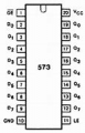
We can assume that the two rotary switches connect to one 74HCT573 for 8-bit input to the MCU.

The resistor array in a SIP package could be pull-up or pull-down. We don't know as yet.
Let us assume that they are pull-up resistors on the input pins 2 to 9 at device D5.

1678201914563.png

Focus on one rotary switch at a time. Set the switch from 0 to 9.
With power OFF, measure the resistance from pins 2-9 to GND.

We will assume that the LEFT rotary switch is encoded to D7-D4 and the RIGHT rotary switch is encoded to D3-D0.
We will soon find out.
 

Thread Starter

geoffers

Joined Oct 25, 2010
520
That's right, left to d7-d4 right d3-d0.
They are pull-ups, the common of the switches is to ground.

Next question! I assumed oe would be connected to the micro so it can use the buffer to put the data 'on' it's port?

I can't find that it is yet!

Thanks for the help
Geoff
 

MrChips

Joined Oct 2, 2009
35,018
Now that we have confirmation on the pull-ups and nybble order, the next step would be to check that the 0-9 selection presents the correct BCD bits to the 74HCT573 latch.
 

Thread Starter

geoffers

Joined Oct 25, 2010
520
And it is, via a 74hct139 multiplex!

Guess the best thing is to get a the scope on it in the morning and check oe is being cycled on power up, then check the output from the buffer?

Cheers Geoff
 

Thread Starter

geoffers

Joined Oct 25, 2010
520
The switches do present the right encoding to the buffer.

Checking the output could be tricky as I think oe should only be enabled for a short period to send the address to the micro port.

Cheers Geoff
 

Thread Starter

geoffers

Joined Oct 25, 2010
520
Thanks again for the help, I'm going to set up to scope the pins in a bit.

I'd just like to understand a bit more about what I'm dealing with!

The main processor is 80c32 just flicking through data sheets it seems it has no ROM? An I correct?

The program is held in the 27c256 eprom on the board?

Does this mean nothing is programmed into the 80c30?

I know the eprom works on the good board, if the processor is duff could I just swap it is what I'm getting at or is there configuration held in it somewhere?

This is all new to me even though it's old!

Cheers Geoff
 

ericgibbs

Joined Jan 29, 2010
21,531
Hi Geoff,
On the 80C32 only 256*8 RAM.
No programming for the 80C32
The 27C256 EPROM is programmed with the Code.
The quick way to check the MCU is to try swapping the 80C32.

E
 

Thread Starter

geoffers

Joined Oct 25, 2010
520
Thanks Eric,
That gives me a bit of hope, I know I have a good program as the other board runs as expected.

Also means I got it from a crook! He said it was working fine :mad:

The processor is soldered in so I'll have a poke around with my scope and try to get a idea what's going on.

If I have to take it off I'll put a dip socket in there.

Cheers Geoff
 

ericgibbs

Joined Jan 29, 2010
21,531
hi Geoff,
If the 80C32 is soldered in, I would advise you not to try to remove it, you will most likely damage the MCU and PCB.

E
BTW: why do you think the 80C32 is faulty.?
 

ericgibbs

Joined Jan 29, 2010
21,531
Hi Geoff,
Do you have the equipment which will enable you to say Erase the 27C256 EPROM and then reprogram it.?
E.
BTW: I was under the 'wrong' impression that your 80C32 was located using a DIP plug in socket.


Footnote: I guess you realise that if you are able to Read the code in the 27C256, you will have to save that program in a device that will be able to to be Read by a programmer device, when programming a new 27C256.?
 

Thread Starter

geoffers

Joined Oct 25, 2010
520
Hi Eric,

I'm not sure at the moment, hopefully it will be the buffer chip as that's easier to change, was more interested in how the whole setup worked, so I can narrow things down bit by bit!

However I now know that it might still be possible to repair even if it is the 80c32!

Cheers Geoff
 

Thread Starter

geoffers

Joined Oct 25, 2010
520
The board is on a bus, each board has its own node number.
I have 2 robots each with identical boards, one of the boards developed I think a regulator fault which cooked most of the IC's on it.

I managed to get a replacement board second hand (assured it was working!)

It won't show it's self on the bus, if I swap the eproms the good board still works so the eprom is ok.

When the good board boots it displays 2 red LEDs briefly then starts talking on the bus when they go out.

The replacement board lights these LEDs and they don't go out, the green one blinks which makes me think the processor should be ok so I was looking at the part of the circuit that sets the node address.

If that's working ok (not checked yet) then it's only really the processor left?

Sorry if I'm rambling!

Cheers Geoff
 
Top



