24vac to 12vdc converter circuit

Thread Starter

shahnawazpathan7

Joined Jan 14, 2019
20
Under a low (weak) load the transformer output will typically be 5-10% higher than the rated value (it's designed for 24Vac output at full load).
This means the rectified output voltage could exceed 35V, which is the 7812 limit.
You thus might consider Bordodynov's two 7812 circuit in post #6.
It distributes both the voltage and the power dissipated between the two.

Out of this 3A. I have only 1A available for my application. As the transformer is mainly powering a camera.
Sorry I didnt mention that earlier considering it unnecessary.
 

Thread Starter

shahnawazpathan7

Joined Jan 14, 2019
20
hi 7,
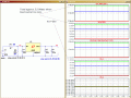
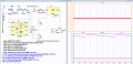
This is another way, a very inefficient option, it will work, I am posting for reference only.
Its a resistive divider on the 7812 input, using 3-5W resistors.
Ask if you need explanation of the plots.
E
Hi eric,

If you think it shall work then I can try it. In what terms it is inefficient?
 

ericgibbs

Joined Jan 29, 2010
21,477
hi 7,
Its using current just to heat the R1 and R2 power resistors, [about 2.5Watts ] even when the Vout is open circuit, ie: supplying no load current.
Check the simulation plots for o/c Vout.
E
 

Attachments

Thread Starter

shahnawazpathan7

Joined Jan 14, 2019
20
hi 7,
Its using current just to heat the R1 and R2 power resistors, [about 2.5Watts ] even when the Vout is open circuit, ie: supplying no load current.
Check the simulation plots for o/c Vout.
E
I think there wont be any case when output will fall to zero as this transformer is powering a camera mainly in the current range of 1A to 2.5A. Still if you have any better proposal than this which is kind o efficient then plz do mention it too. I shall compare both o them.

Shan
 

Tonyr1084

Joined Sep 24, 2015
9,744
Beginning to think maybe two different power sources would be a better solution. Since we don't know the full application of what you want to implement or how you wish to go about it we can't be completely clear on what the best route would be.

From what I'm reading, you have a camera operating from the 24 VAC source. You want to use some sort of sensing system to operate a relay, possibly to turn the camera on. Correct me if I'm wrong. But you don't need to completely depend on the 24 VAC source to operate the camera AND the sense/control circuitry.

I don't know what you already have toward accomplishing your goal, but you might want to consider a small wall wart 12 volts or even 5 volts since 5 is far more common and use that with your sensing circuit to operate a 5 volt relay instead of a 12 volt relay. This way you leave your transformer completely alone and unencumbered with not only providing power for the camera but also powering the sense circuit. It may be more efficient to do that, but there's a lot more waste in knocking 24 volts all the way down to 12 volts. Since you need so little power a small wall wart would likely fit the bill. The relay isolates the one circuit from the other. The relay is only acting like a switch for something else. In that instance you can use that relay to power any number of voltages, let alone just 24 volts. AC or DC, the relay contacts don't care. As long as you're within the rating of the relay you should be good to go.

Earlier I mentioned auto voltages. I guess I was off with that thinking. A 24 volt camera system is obviously not intended for a car. Whatever you're doing with your project, the more we know about your goal the better we can help you reach a good solution. Opinions will vary on what the best route may be. It's my opinion you would want PWM over regulation. However, opinions are like arse holes. Everybody has one. Many stink. Whatever solution you pursue, the choice is yours. Knowing a little more about what you're attempting to accomplish, I now think I'd opt for a second power source for the sensor circuitry. And at that, I might opt for 5 volts versus 12 volts.

The choice is yours. Let us know more (all) about what you're working towards and I am confident you'll get really good answers here. My contemporaries have shown time and again to have a thorough understanding of electronics and engineering. We only ask you don't request of us to engineer a solution FOR you.
 

crutschow

Joined Mar 14, 2008
38,574
Is there any way to use only one 7812 IC instead two?
You could add some diodes in series with the bridge output to reduce the voltage.

Otherwise you could use an LM317 regulator, which is good up to 40V.
It requires just two 1% resistors to set the output voltage.
 
Last edited:

MisterBill2

Joined Jan 23, 2018
27,739
One choice not yet mentioned is a small transformer with a 2:1 stepdown ratio. That would provide the required 12 volts more efficiently than any other method mentioned so far. Or it could be a simple autotransformer used for the stepdown. The best part is no design work required. Also it would be more reliable than many of the mentioned options.
 

MrChips

Joined Oct 2, 2009
34,948
If you only need 50mA @ 12V, I would consider using a 470Ω 2W resistor in series before the input of a LM7812 voltage regulator.
 

Andrei Suditu

Joined Jul 27, 2016
52
Don't know if this was already mentioned ,but you could use a dc-dc converter since it will drastically reduce the disipated power.
There are some cheap chinese versions readily available but may not be the best choice since the inductor should be optimized for a specific case scenario(Vin,Imax_out,Vout).
Anyway even the cheap ones won't disipate 2W of power which is a lot of heat.
If you need something really well regulated you could pair the dc/dc converter with a linear post regulator.
For the DIY variant look into the cheap variants of:LM2576,LM2596,MC34063.
 

Thread Starter

shahnawazpathan7

Joined Jan 14, 2019
20
Hello guys,

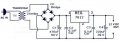
I have tested the circuit and as expected the rectified voltage to 7812 is 36.4v and it is heating even if I have connected it with a heat sink. As of now I have only operated a 12v relay and a sensor device consuming 150mA out od 3A 24vac transformer. Is that the cause of heating up the regulator.? if so can I use some diodes to reduce exceeding 1.4v to IC.
Will that help ?
Any suggestions?

Regards,
Shan

main-qimg-541ed2a7b7392c242d64ce1f8586e81b-c.jpg
 

Tonyr1084

Joined Sep 24, 2015
9,744
The reason why a regulator like that heats up is because it's receiving so much power and providing a regulated (lower) power. For a moment lets use some wildly exaggerated numbers that don't exist in the real world: Suppose you have a power supply that supplies 1,200 volts and you want to regulate it down to 12 volts. While you're getting the desired 12 volts you have to do something with the remaining 1,188 volts. You're not just blocking that excess voltage you're converting it into a different form of energy. Energy that exists as 1200 volts is still the same amount of energy whether you keep it as electric pressure (the correct term for voltage) or if you convert it to thermal energy (heat). Since I'm using a wild number as an example, your regulator must convert 1188 volts (assume at 3 amps) (that's 1188 x 3 = 3564 watts) your regulator must do something with that 3500 watts. It's converted into heat. That's the main reason why people are suggesting PWM (Pulse Width Modulation) as a means for reducing the voltage.

The way PWM works (in your real world situation) (24 volts to 12 volts) is that it turns ON and OFF rapidly. The difference between the on time and the off time gives you an average voltage. So if 24 volts is on half the time and off half the time then the average voltage is 12 volts. It's not converting (wasting) extra voltage, it's merely shutting it off for a short period of time. DC to DC buck converters do exactly that - turn on and off to give you an average voltage output.

All things have their limits, so you have to consider three factors: Voltage in and out; Amperage; and Wattage. If you exceed the device's capabilities you will burn it out. No matter what you do with a 7812 it's going to have to dissipate the unused power. It doesn't just go away, it goes away as heat. That's the nature of 7800 regulators.
 

Thread Starter

shahnawazpathan7

Joined Jan 14, 2019
20
hi 7,
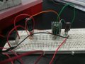
What size is the heat sink and what is its operating temperature.?
A photo of the project would help.
E
---------------------------------------------------------------------
Well, Its small in size. I really don't know about operating temperature. Just found in a local vendor. Picture is attached.
15487735912281380983632.jpg
 
Top