
I was trying to see if I could fix this linear power supply, and lo and behold, my multimeter probes slipped causing it to short "totally".
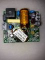
The top red circle is where the mains come in, and at the bottom red circle, they convert to 24DC (or so, didn't really get a decent measure..)
Now how in the world does it go from 230 AC to 24V DC through that little IC, and without a sink? The numbers in the chip are too damaged to read anything, all I can see is a sine wave on the left side and a +/- on the right.
This circuit looks overly complicated, too, with all these IC's and tiny transistors. Could someone give a shot in the dark as to how it works, just overall? Like what is the large inductor for, and what is the large cap for. Maybe someone has experience with this.
I was going to repair this, until I broke it. Now I wan't to make something that just does the job in a good-enough manner. Just for fun, I guess.
This LPS is feeding a CCTV station, I don't know anything about amp usage, sadly.
Attachments
-
 1.6 MB Views: 43
 -
 1.1 MB Views: 42


