Facebook
 Google
 GitHub
 Linkedin
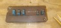
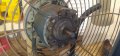
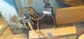
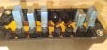
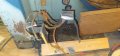
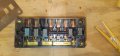
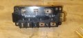
I have an old lasko window fan that works but the switch got sticky and stopped working. It is a 2 speed reversible motor. The switch was an Ark-les switch which used slides to make the contacts. The wiring diagram has been long gone but after lots of tests I've come up with which wires need to go where. It also has a 3 MFD capacitor My question... is the a way to wire this with toggle switches or do I need to get something else?
Low - Forward
Hot, 2, 4
1(INS)
Com, 3, 5
Low - Reverse
Hot, 2, 5
1(INS)
Com, 4, 3
High - Forward
Hot, 1
2, 4
Com, 5, 3
High - Reverse
Hot, 1
2, 5
Com, 4, 3
any help at all would be greatly appreciated!
Low - Forward
Hot, 2, 4
1(INS)
Com, 3, 5
Low - Reverse
Hot, 2, 5
1(INS)
Com, 4, 3
High - Forward
Hot, 1
2, 4
Com, 5, 3
High - Reverse
Hot, 1
2, 5
Com, 4, 3
any help at all would be greatly appreciated!
Last edited: