2 opamps in series activate one gate

Thread Starter

barg

Joined Dec 23, 2015
129
Hi All,

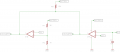
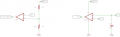
I would like to use 2 channel opamp as the attached schematic, to operate 1 N-fet gate.

One of the channel is a sensor threshold and the other channel is for low battery threshold, so the N-Fet gate should receive voltage only if two of the channels will output together, if one of them is not outputting, the Gate should stay low.

Question is how to connect the two outputs so they will control 1 N-fet gate? is the layout in the schematic is correct?

Thanks in advance,

Barg
 

Attachments

MrChips

Joined Oct 2, 2009
34,841
You are attempting to implement a boolean logic AND condition.
You can do this with off-the-shelf logic gates or you can DIY with resistors, diodes and transistors.
Thus, you will need two logic outputs from your amplifiers. Traditionally, this is accomplished with analog comparator circuits.
 

LesJones

Joined Jan 8, 2017
4,511
You could do what you specify by connecting a diode between the output of each op amp (cathode end.) and the anodes of the diodes joined together and to a pull up resistor. This point would also be connected to the gate of the N-FET. If you could use a dual comparator (Such as an LM393) you would not need the diodes. Just connect the two outputs together and to the pull up resistor and to the gate of the N-FET.

Les.
 

Thread Starter

barg

Joined Dec 23, 2015
129
Thanks for your reply.

I have also lm393 in hands but I don't understand how you do the connections, can you advice based on the updated schematic?

As to Mr. Chips to use Logic and, It will take time until I get it, I will try to solve it now in this way.
 

Attachments

LesJones

Joined Jan 8, 2017
4,511
The schematic that you have just posted in post #4 is exactly how I described. Unless your question is now about the input side of the comparators. If this is the case then you will need to give details of the sensor, battery voltage and the way you are generating the 5 volt reference.

Les.
 

Thread Starter

barg

Joined Dec 23, 2015
129
Yes, I refer to the two outputs, if that is correct, that is great. as for the inputs, I am good.

if talking of comparing this solution as you suggested with lm393 vs using AND ic, which of the two options is more reliable? can you advice for that?

I am asking as I don't understand in case of one of the outputs will be high and the other will be off, how this pull up resistor or lm393 will prevent from the voltage to go to the mosfet gate?

Thanks
 

LesJones

Joined Jan 8, 2017
4,511
The dual comparator would be very slightly more reliable as there would be one less component to fail. The disadvantage of the dual comparator solution is that it would make fault finding more difficult as you could not tell which comparator was holding the output low. Using a logic gate or diodes would allow you to see the ouput of each op amp / comparator before they were "anded" together.

Les.
 

Thread Starter

barg

Joined Dec 23, 2015
129
Yes, I agree for less components less potential problems but I don't understand your second part of your answer, did you meant for monitoring or certainty that sometimes only one output can send high to the gate? if its monitoring to see in real time which one is outputting high/low - well I don't mind for that.
 

ebeowulf17

Joined Aug 12, 2014
3,307
You could do what you specify by connecting a diode between the output of each op amp (cathode end.) and the anodes of the diodes joined together and to a pull up resistor. This point would also be connected to the gate of the N-FET. If you could use a dual comparator (Such as an LM393) you would not need the diodes. Just connect the two outputs together and to the pull up resistor and to the gate of the N-FET.

Les.
I was really confused by this description at first. Am I right in thinking that this only works because the LM393 has an open-collector output stage? If a comparator with push-pull outputs was used, the two comparator outputs would just be fighting each other, right?
 
Top