 Facebook
 Google
 GitHub
 Linkedin
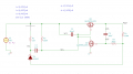
Hi all, I'm attempting to model this Fig 1 circuit. I've attached a diagram of my kicad model (so I'll use the built in ngspice modeling). I'm attempting to just model what happens just after the power is applied, so the switch isn't involved and is not modeled. The circuit has a jumper in it and I've modeled it both ways; I've attached images of both of those.
As suggested by the website with the original circuit diagram (at the bottom), I've configured the PMOS as a IRF7317P and the NMOS as an IRF7317N and I've using those spice models from the manufacturer. I've taken care to ensure those models match the pins of the schematic. I'm using a 1N4002RL for the diode (I'm not sure how to check the pin order of this). See the zip file attached which has the whole kicad project including these simulation libraries.
When I run the simulation and measure V(/POUT) I expect it to be reach a steady state of 4.2V in the auto_on schematic and 0V in the auto_off schematic, but in both cases it converges to 4.2V. As you can see from the labels I'm using the transient analysis with a variety of initial conditions set. I also tried a piecewise-linear DC model which applies 4.2V at 100ms and it also shows V(/POUT) converge to 4.2V.
I really don't know what I'm doing with the initial conditions section. With each one I set, I get very different results. What would you do for the initial conditions?
An ideas why this doesn't model the way the description on the reference page suggests it should?
Do you expect the auto_on schematic to converge at 4.2V? A bit of explanation of what you expect the auto_off to do just after power is applied from someone more experienced would be really nice.
Any advice, or questions is welcome. Thank you!
Attachments
-
 12.1 KB Views: 21
 -
 12.4 KB Views: 19
 -
226 KB Views: 6
Last edited:


