Facebook
 Google
 GitHub
 Linkedin
Hello,
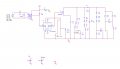
I am trying to make a High Voltage Power pulse generator with
Requirements
Amp output: 15 A
Voltage Output: 100V
Rise: <=1 us
Width: <= 100 um
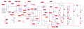
which is when I came across this schematic

As i was trying to simulate the schematic, I noticed I noticed that could not find the Optocoupler in Pspice:

I was wondering if anyone knew what is the name of this Optocoupler for Pspice simulation or a replacement Optocoupler to simulate it:
I am trying to make a High Voltage Power pulse generator with
Requirements
Amp output: 15 A
Voltage Output: 100V
Rise: <=1 us
Width: <= 100 um
which is when I came across this schematic
As i was trying to simulate the schematic, I noticed I noticed that could not find the Optocoupler in Pspice:
I was wondering if anyone knew what is the name of this Optocoupler for Pspice simulation or a replacement Optocoupler to simulate it: