1kHz sine wave amplifier

Thread Starter

Jayvin

Joined Mar 8, 2015
47
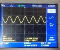
Hello guys, i am here with a new question and i need some insight. I have sine signal (in picture) which i have to amplify to about 12V which i have then to step it up using a transformer.

The signal is from a microcontroller. I do not want to connect the transformer directly to the microcontroller. I have a 6-0-6 transformer.. from 240 volts. that is a ratio of 1:40

I have tested the system with a signal generator. It works but doesnt do that well with the microcontroller.

I have tried using an op amp amplifier, but the output became zero when i connected the transformer.
 

Attachments

wayneh

Joined Sep 9, 2010
18,106
You need a transistor amplifier just like you would use for audio. In fact you could buy yourself a ready-made audio amp off e-bay for cheap, if you don't already have one.

It would help to know the impedance of your transformer at the frequency you want, just as you would want to know the impedance of a speaker.
 

Thread Starter

Jayvin

Joined Mar 8, 2015
47
You need a transistor amplifier just like you would use for audio. In fact you could buy yourself a ready-made audio amp off e-bay for cheap, if you don't already have one.

It would help to know the impedance of your transformer at the frequency you want, just as you would want to know the impedance of a speaker.
How do i find the impedance of the transformer?
 

wayneh

Joined Sep 9, 2010
18,106
You can start with the DC resistance, but at 1kHz the impedance is likely dominated by the inductance portion of the impedance. Without an inductance meter, the best you could do is calculate an estimate.

On the upside, the impedance is probably larger than what an audio amp is designed for, so an audio amp will likely be fine. Easy enough to try.
 

Papabravo

Joined Feb 24, 2006
22,083
How do i find the impedance of the transformer?
You consult a datasheet or you measure it with an appropriate piece of equipment.
The problem you had was that the impedance of the transformer was so low you could not supply any current to energize the windings. Opamps are good for about 50 milliamps. Into a stepup transformer that 50 milliamps will turn into microamps.
 

Thread Starter

Jayvin

Joined Mar 8, 2015
47
You can start with the DC resistance, but at 1kHz the impedance is likely dominated by the inductance portion of the impedance. Without an inductance meter, the best you could do is calculate an estimate.

On the upside, the impedance is probably larger than what an audio amp is designed for, so an audio amp will likely be fine. Easy enough to try.
Would something like this one possibly work?
http://www.ebay.com/itm/Power-Suppl...601?pt=LH_DefaultDomain_0&hash=item3ce41065a1
 

wayneh

Joined Sep 9, 2010
18,106
That's exactly the sort of thing I was referring to. However if you need a full 12V peak-to-peak output, whatever amp you choose will need to work on a supply higher than 12V, like 15V or more. So I'm a little worried that particular one might not be rated to that higher voltage. If you can live with <12V at the output, that one might be fine.
 

Thread Starter

Jayvin

Joined Mar 8, 2015
47
That's exactly the sort of thing I was referring to. However if you need a full 12V peak-to-peak output, whatever amp you choose will need to work on a supply higher than 12V, like 15V or more. So I'm a little worried that particular one might not be rated to that higher voltage. If you can live with <12V at the output, that one might be fine.
Yeah. it would be fine up to 10V. thank you.
 

wayneh

Joined Sep 9, 2010
18,106
How much power do you need at the secondary? It's possible the impedance of that transformer at 1kHz will not allow much current - or power - to pass.

I think that amp will do what you said you wanted, but that doesn't mean the end result will be what you want.
 

Papabravo

Joined Feb 24, 2006
22,083
That's a start. Having the datasheet for the part is the first step. I was more interested in the schematic for the module. In particular how the inputs and output are coupled to see if it would be suitable, or modifiable for directly driving a transformer. It doesn't look like there are enough components on the board to duplicate the test circuit from the datasheet. It looks like the part is good for ±16V supplies.
 

Thread Starter

Jayvin

Joined Mar 8, 2015
47
actually it will be open circuited. or i might just add a load of about 3.3 MOhms. I just wanted the signal. so that i can generate an electromagnetic field.
 

SgtWookie

Joined Jul 17, 2007
22,230
Is the transformer designed for your desired operating frequency range?
Typical "power supply" type E-core laminated transformers are designed for a range of about 47Hz to 63Hz; outside of that range they are very "lossy".

By the way, if the secondary is 6-0-6, that means the output AC was originally supposed to be ~17V peak to peak, or 8.5v-0-8.5v peak to peak, at the rated VA (volt-amperes)
 

Papabravo

Joined Feb 24, 2006
22,083
What "lossy" means in layman's terms is that even if you put a signal that is say 24V P-P or -12 to +12 in, you might not get anything interesting out because that power transformer will so attenuate and distort your waveform that nothing will be left. This result should not surprise you. Inductors don't really like high frequencies.

An audio coupling transformer with specified input and output impedance may work better for you in this application.
 
Top