180V DC motor Board Questions..

Thread Starter

taji

Joined Nov 21, 2017
2
hi, guys and girls i need some help with a treadmill motor control board i have ,,well i have 4 of these that i salvaged from junkyard with the motors. i was going to throw them ( the boards) into recycling bin then i decided to test them and to my surprise 3 of them are good.. i have a very very very limited knowledge of electronics ( machinist by trade) so here's the problem that i need solution for...my goal is to use these boards to control just the speed of the motors and use only the high voltage (180v) part of the circuit without using all the top panels and gear a treadmill uses..i've searched on net and only way people are using these boards is with a pwm device..
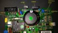
i've included some pics of one of these boards with descriptions..and here are a few questions...
1) in a normal treadmill setup the PWM signal from the top panel of the treadmill goes to the G30N60 mosfet through a lot of other resistors and IC's etc . can a small circuit be made to send and control that signal straight to the G30N60??
2)one very crafty gentleman made a 50ms period variable duty cycle Square wave PWM Driver to control the speed on his (MC-2100 ) board but my board's totally different from his but can it still be used with some mods on to my board?? ( i've attached the drawing below)
i just want to get rid of all the additional treadmill functions and only use just necessary components on these board if possible..
pls help..
cheers Treadmill board 3.jpg Treadmill board 3.jpg treadmill controller board.jpg treadmill board 2.jpg P_20171118_212031.jpg P_20171118_212257.jpg MC2100 PWM Driver v6.png Treadmill board 3.jpg
 

Attachments

Tonyr1084

Joined Sep 24, 2015
7,899
Not the expert here, but I've salvaged several motors and speed control boards too. The ones I have are likewise typically controlled by PWM. However, some of them were controlled simply by a potentiometer creating a voltage drop. And the PWM units can just as easily be controlled (the ones I have) by connecting a potentiometer to the small red and black wires coming from the board and the wiper connected to the white wire.

In experimentation I discovered that by shorting the red and white wires I got full speed. Shorting the black and white together gave me zero speed. By throwing a 50K pot across the red and black wires and pinning the white wire to the wiper, I gained full control over the speed. At present I have a bandsaw that I'm driving with an old treadmill motor and control board. I control the speed with the 50KΩ pot.

I don't see on your board where that would be. Since I'm not the expert I can't really tell you exactly where to connect what. But I DO believe it would be a mistake to try and connect something to the circuitry mid-stream without knowing exactly what you're doing.

If you truly want a PWM module, go to an automotive junk yard and scavenge some of the light dimmers out of a late 80's Toyota. I have an 89 Toyota Celica dash board dimmer that behaves as a load follower (if I'm saying that right) (Power to the dash lights then to the dimmer then to ground. And yes, there are three wires with that. You need power to run the PWM. Sorry, I'm not at my workbench or I'd grab it and tell you a little more about it.

Hope this helps.
 

Tonyr1084

Joined Sep 24, 2015
7,899
Here's my thoughts on where you will likely control the motor speed. Keep in mind I've already said I'm not the expert; so act accordingly. Anything you try - you try at your own risk of damaging the board. If this were mine, I'd try it.

TM Speed Control.jpg
 

MaxHeadRoom

Joined Jul 18, 2013
28,686
Incidentally most of the analogue controllers use a 10k pot, most even work with a 5k.
Whatever it is, ensure it is linear and not log.
Max.
 

Thread Starter

taji

Joined Nov 21, 2017
2
Here's my thoughts on where you will likely control the motor speed. Keep in mind I've already said I'm not the expert; so act accordingly. Anything you try - you try at your own risk of damaging the board. If this were mine, I'd try it.

View attachment 139943
hi tonyr , mate, thanks for the reply ,,that connector you mentioned above is for motor rpm sensor in feed..there's a rpm sensor at the back motor and it connects to that three pin connector (one you mentioned) to give the controller feedback on how fast is motor running.. i've done a bit more research( if you can call googling research..lol) and no luck. i've drawn a basic circuit, layout of the components on the board and how they are connected ..again my only goal is to somehow control the motor speed using PWM to maintain good torque on low RPM's.(planning to run it on a milling machine with it..please help if possible...cheersdc motor circuit.jpeg
 

Tonyr1084

Joined Sep 24, 2015
7,899
Unfortunately the ones I'm familiar with use BEMF (Back Electro Motive Force) to monitor the speed (RPM) of the motor. It's looking like you have a board I'm unfamiliar with. I did notice another 3 pin connector just to the right of the one I pointed out. Can't tell anything about it from here, but maybe THAT is where the motor speed is set. I'm guessing here. Nothing more than blind groping for a possible solution. Unless that other 3 pin connector is the motor speed set control then I can't give you any further guidance. The ones I have are older models. Every single one I've had in my possession were controlled by the manor I described.

Good luck.
 
Top