12V FAN speed control by temperature

Thread Starter

extrememod2020

Joined Nov 30, 2021
20
Hi guys,

If anyone can help me I'm willing to make a donation for your time. Here's the schematics I'm looking for including some component specs:

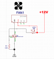
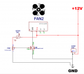
DC Fan (12V) speed control circuit dependent on temperature ranging from 25 to 100 degrees Celsius with smooth changes in speed all the way up to 100% speed at 100 degrees Celsius

**Fan specs: 12V 1A**

Project requirements:

1. Minimal amount of through-hole components (SMD components are preferred)
2. Correct thermistor probe model or specs for it
3. SMD led lights to indicate ON, 25%, 50%, 75% and 100% fan speed
4. [OPTIONAL] SMD Potentiometer such as TC33X-2-502E but with the right resistance for the circuit
 

AnalogKid

Joined Aug 1, 2013
11,042
Sounds like school work. I'm willing to look at what you have done so far.

Hint: small tubeaxial fans such as yours do not run well at low speeds. Consider setting 50% of full speed, or 50% of its rated operating voltage, as the low limit equal to 25 DegC.

What is the function of the SMD potentiometer?

ak
 

Thread Starter

extrememod2020

Joined Nov 30, 2021
20
Sounds like school work. I'm willing to look at what you have done so far.

Hint: small tubeaxial fans such as yours do not run well at low speeds. Consider setting 50% of full speed, or 50% of its rated operating voltage, as the low limit equal to 25 DegC.

What is the function of the SMD potentiometer?

ak
Actually I'm not an electrical engineer, just starting out. Normally I can always find some tutorial and follow that to build but for this I can't seem to find info or tutorials on how to build such device. I'm an Android Head Unit modder and look to create a small pcb circuit to control 1x 12V fan.

Normally I'd use thermal switches (normally open, negative connection control) but look to upgrade to a more sophisticated temp/speed control system as the fans can run pretty noisy at 100%.

Drawing included but I know it's incorrect as my simulation fails. Also it doesn't have potentiometer and no leds (although leds are optional, as the PCB will be inside the head unit).

I think it's "easier" to include the SMD potentiometer to be able to fixate the speed for different fans rather than work with resistors. I'm very novice here.
 

Attachments

AnalogKid

Joined Aug 1, 2013
11,042
"Simulation fails" is not an actual diagnostic, as there are 6.023 x 10^23 possible reasons for that, none of which have anything to do with the circuit. But I digress.

The circuit should work if you get the right ratio between R1 and NTC1. But it will go from low speed to max speed over a pretty small temperature range, and the increase will be non-linear with respect to temperature. This is because an NTC thermistor temperature response is very non-linear, a modified form of exponential. There are circuit tricks to linearize the response curve over a defined temperature range, but 75 DegC is a pretty wide range; the error from true linearity will be 10% or more. AND, once you linearize it, you will find that fan speed is not a linear function of either its DC operating voltage or, if you go that route, its PWM percentage.

Note - I'm not trying to discourage you in any way, just fill in that a smooth, proportional temperature-to-fan-speed system can be approached, but is very difficult to nail open-loop. One "right" way is to get a tach signal from the fan, convert it to a DC voltage, and compare that an adjustable set point to derive the correct fan power voltage. Very much like a linear power supply.

Another note: fans with this type of temperature control built-in appeared in the 90's. With a constant supply voltage, a common model went from 50% to 100% fan speed over the range of 25DegC to 35DegC.

ak
 
Last edited:

Thread Starter

extrememod2020

Joined Nov 30, 2021
20
"Simulation fails" is not an actual diagnostic, as there are 6.023 x 10^23 possible reasons for that, none of which have anything to do with the circuit. But I digress.

The circuit should work if you get the right ratio between R1 and NTC1. But it will go from low speed to max speed over a pretty small temperature range, and the increase will be non-linear with respect to temperature. This is because an NTC thermistor temperature response is very non-linear, a modified form of exponential. There are circuit tricks to linearize the response curve over a defined temperature range, but 75 DegC is a pretty wide range; the error from true linearity will be 10% or more. AND, once you linearize it, you will find that fan speed is not a linear function of either its DC operating voltage or, if you go that route, its PWM percentage.

Note - I'm not trying to discourage you in any way, just fill in that a smooth, proportional temperature-to-fan-speed system can be approached, but is very difficult to nail open-loop. One "right" way is to get a tach signal from the fan, convert it to a DC voltage, and compare that an adjustable set point to derive the correct fan power voltage. Very much like a linear power supply.

Another note: fans with this type of temperature control built-in appeared in the 90's. With a constant supply voltage, a common model went from 50% to 100% fan speed over the range of 25DegC to 35DegC.

ak
These are some great insights. Really helpful. The circuit diagram is outdated. Here's the most current one and I managed to integrate the potentiometer (I hope).

I have seen circuits on eBay where you can run the speed at 4 stages - 25%, 50%, 75% and 100% - this solution would also be more than acceptable. In this case I would want to "assign" the speed percentages to the temperature levels. Example:

40°C = 25% speed
55°C = 50% speed
70°C = 75% speed
85°C or more = 100% speed

The fans are PWM to begin with but the android pcb's do not support such feature unlike PC's.
 

Attachments

Thread Starter

extrememod2020

Joined Nov 30, 2021
20
These are some great insights. Really helpful. The circuit diagram is outdated. Here's the most current one and I managed to integrate the potentiometer (I hope).

I have seen circuits on eBay where you can run the speed at 4 stages - 25%, 50%, 75% and 100% - this solution would also be more than acceptable. In this case I would want to "assign" the speed percentages to the temperature levels. Example:

40°C = 25% speed
55°C = 50% speed
70°C = 75% speed
85°C or more = 100% speed

The fans are PWM to begin with but the android pcb's do not support such feature unlike PC's.
Here's what I'm using for a router fan mod: link It can be set to variable speed depending on temp with a fairly good range:

TFL (No. 1): The lowest temperature channel PWM setting, when ON state FAN1 PWM minimum is 40%, when OFF the minimum PWM of FAN1 is 20%.

TP1 TP2 (No. 2,3): Temperature channel control temperature zones are interpreted as follows (need to used with the temperature probe):

TP1 TP2 Accelerating temperature Full speed temperature
OFF OFF 35℃ 45℃
ON OFF 40℃ 55℃
OFF ON 50℃ 70℃
ON ON 60℃ 90℃
 

Thread Starter

extrememod2020

Joined Nov 30, 2021
20
I'm also happy to reduce the temperature range for the fan to start at 50°C and to run at max at 100 °C.

If PWM is still the best and only option, then I can try to program the STM8S003F3 chip that seems to be used on these pcb's you can get on eBay.

The reason I don't just buy one is because I need custom-shape pcb that I design and print.
 

AnalogKid

Joined Aug 1, 2013
11,042
1. Reference Designators - !

2. The 1 K resistor above the 100K resistor, the one connected to the 555 Vcc pin - why? You do not want ***any*** resistance between the chip power input and the power source. It looks like you are trying to run the chip on 5 V while the thermistor and everything else runs on 12 V. Why? If you really want to do that, the 47 nF decoupling cap is way too small to matter. That's where the 100 uF cap should be.

ak
 

Thread Starter

extrememod2020

Joined Nov 30, 2021
20
1. Reference Designators - !

2. The 1 K resistor above the 100K resistor, the one connected to the 555 Vcc pin - why? You do not want ***any*** resistance between the chip power input and the power source. It looks like you are trying to run the chip on 5 V while the thermistor and everything else runs on 12 V. Why? If you really want to do that, the 47 nF decoupling cap is way too small to matter. That's where the 100 uF cap should be.
ak
This is because I'm running a 12V 1A fan. I modified this original drawing, supposedly done by a proper electrical engineer. All I've done is to replace the TIP122 transistor with a MOSFET one, and the 2.7k resistor replaced by a potentiometer. Please see (original) drawing attached.

Here's how it's supposed to work:
  • The 12V DC Fan is powered by the PWM pulses from the SE555 whose pulse rate cycle goes down from around 34% at room temperature (minimum speed) to 100% (maximum speed) when the temperature has reached a high.
    [*]These pulses are generated by SE555 which is rigged to work as an integrated voltage controlled oscillator circuit. On the control voltage pin 5 a varying voltage is applied determined by the resistance of the thermistor.
    [*]The 100uF capacitor connected in parallel with the thermistor shorts the supply with pin5 of the IC simulating a high temperature state for a few seconds during power switch ON so that the FAN motor gets an initialization torque and is prevented from getting stalled.
    [*]The voltage to the IC 555 is regulated by the zener diode of 5,1V so that it allows the IC to work regardless of the input supply fluctuations.
    [*]To adjust the temperature triggering threshold at which the Fan may be expected to speed up, the 2.7k resistor has been changed to a potentiometer to pin 5 of SE555.
    [*]I'm also thinking of changing the 10k resistor from pin3 to the transistor to something like 1k-2.2k as mosfet doesn't require as much as BJT, unless totally mistaken?

PWM is still an option (i.e building a circuit and programming the chip) but I'm really trying to find an analog way of solving this. As mentioned, the most critical temp control range is 50 - 100 °C.
Really appreciate all of your input thus far. Cheers
 

Attachments

Last edited:

ElectricSpidey

Joined Dec 2, 2017
2,778
First thing...that schematic does not produce PWM, it's variable frequency.
Second the drive current for the NPN base is only something like .0003A providing maybe 3mA for the motor.
And, whoever thinks a 10k resistor provides "more" than a lower value resistor needs to go back to school.

If you want to use that circuit, ditch the Zener and the 1k resistor, and use something between 100 and 470 ohms at the gate of your MOSFET.
 
Last edited:

Thread Starter

extrememod2020

Joined Nov 30, 2021
20
First thing...that schematic does not produce PWM, it's variable frequency.
Second the drive current for the NPN base is only something like .0003A providing maybe 3mA for the motor.
And, whoever thinks a 10k resistor provides "more" than a lower value resistor needs to go back to school.

If you want to use that circuit, ditch the Zener and the 1k resistor, and use something between 100 and 470 ohms at the gate of your MOSFET.
Appreciate it thank you. Addin the updated schematic just to make sure I've done it right.

Screenshot 2021-12-02 at 17.36.01.png

Also if there is a better solution based on whatever circuit, happy to explore that. Cheers
 

AnalogKid

Joined Aug 1, 2013
11,042
Thinking about the circuit in post #10, there might be a reason the 555 is running on 5 V while the thermistor voltage divider is driven by 12 V - range.

The Control input to a 555 does very little when used to modulate the output characteristics. Also, the thermistor resistance change *as a percentage of the bias resistor* might not be enough to cause the kind of output change you want. Driving the thermistor string with 12 V and scaling the bias resistor probably produces a larger dV/dTemp at the Control pin input. Hmmm ...

ak
 

Thread Starter

extrememod2020

Joined Nov 30, 2021
20
Thinking about the circuit in post #10, there might be a reason the 555 is running on 5 V while the thermistor voltage divider is driven by 12 V - range.

The Control input to a 555 does very little when used to modulate the output characteristics. Also, the thermistor resistance change *as a percentage of the bias resistor* might not be enough to cause the kind of output change you want. Driving the thermistor string with 12 V and scaling the bias resistor probably produces a larger dV/dTemp at the Control pin input. Hmmm ...

ak
Well, if I am overthinking this due to lack of proper knowledge (still quite a beginner) - would pure PWM circuit be a simpler choice? To reiterate, this module will not be connected to a PC or any i2c.
 

ElectricSpidey

Joined Dec 2, 2017
2,778
When dividing the thermistor on the 12volt rail and having the 555 on 5volts I would be concerned on exceeding the voltage on the CV pin.

But yea, it's certainly true that the change on the output is limited using the CV pin and can't come close to what you could do with PWM.
 

Thread Starter

extrememod2020

Joined Nov 30, 2021
20
When dividing the thermistor on the 12volt rail and having the 555 on 5volts I would be concerned on exceeding the voltage on the CV pin.

But yea, it's certainly true that the change on the output is limited using the CV pin and can't come close to what you could do with PWM.
That's what I was afraid of. Now if I do buy some PWM chips, they come empty and I'll need to use a programmer to upload code? Or is it possible to buy sort of preprogrammed chips somehow?
 

Thread Starter

extrememod2020

Joined Nov 30, 2021
20
The discrete ones I've built are mostly controlled by a pot, but some are a little different, but yea the PSoC boards are programmed.
Okay so if I want a fully automatic DC 12V/1A PWM fan that runs of the temperature levels from the thermal probe covering a range of 40 to 100 degrees Celcius - should I simply buy one of those cheap Chinese ones ad reverse engineer it or rather build something from scratch?
 
Top