 Facebook
 Google
 GitHub
 Linkedin
Im currently designing a 12V DC split air conditioner for a van conversion. I purchased a low-cost kit from China, and the quality and efficiency are very poor, and the systems are way under powered. For these 12v systems to be feasible, they really need to use high quality/efficiency components and motors. They do sell some decent-quality kits you can buy from U.S. manufacturers, but they are way over priced for what they are, and many of those kits don't use the best motor options. My plan is to piece together my own system from quality components,
I have the compressor identified — an inverted 3-phase unit with two options for controlling the three speeds: either PWM duty cycle or ground switching across three control wires.
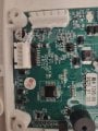
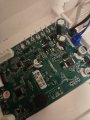
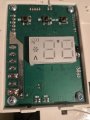
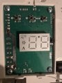
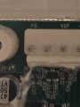
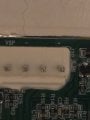
I'm currently working on upgrading the mini split head unit I purchased from China and trying to determine if I can maintain the control board. The unit has a brushed motor that is controlled by two wires and the board also has a 6-pin VSP connector that is unallocated. I have to assume that this would support a 3-phase BLDC Hall motor similar to the ones used in residential systems which are hyper-efficient and quiet. I'm trying to confirm whether the VSP is active and what type of blow motor to purchase.
I can't find any specs on the board, and the manufacturer will not share any information. This appears to be a highly configurable and flexible board that support many different configurations across multiple manufacturers. Is it likely the VSP controller is active. If not, is it realistic to find a way to program/configure the board or will it be locked down? Are there alternatives? Any insights/advice would be appreciated. (board photos attached).
- High-efficiency/quality 12V compressor
- Custom condenser core with dual high quality BLDC high-performance fans
- Mini split-type head unit with BLDC blower (this one is challenging because manufacturers wont disclose control details so you are forced to by their complete kit)
I have the compressor identified — an inverted 3-phase unit with two options for controlling the three speeds: either PWM duty cycle or ground switching across three control wires.
I'm currently working on upgrading the mini split head unit I purchased from China and trying to determine if I can maintain the control board. The unit has a brushed motor that is controlled by two wires and the board also has a 6-pin VSP connector that is unallocated. I have to assume that this would support a 3-phase BLDC Hall motor similar to the ones used in residential systems which are hyper-efficient and quiet. I'm trying to confirm whether the VSP is active and what type of blow motor to purchase.
I can't find any specs on the board, and the manufacturer will not share any information. This appears to be a highly configurable and flexible board that support many different configurations across multiple manufacturers. Is it likely the VSP controller is active. If not, is it realistic to find a way to program/configure the board or will it be locked down? Are there alternatives? Any insights/advice would be appreciated. (board photos attached).
Attachments
-
 1,023.9 KB Views: 9
 -
 1.7 MB Views: 9
 -
 1.6 MB Views: 9
 -
 2.1 MB Views: 8
 -
 1.3 MB Views: 7
 -
 1.1 MB Views: 7


