12V AC motorcycle regulator

Status
Not open for further replies.
I found this article at http://electrosport.com/

AC Lighting - Adding a simple headlight and taillight on your dirtbike.

Follow a few basic guidelines and avoid a headaches.

Bikes that don't come with a lighting coil will need to have one installed. Depending on the model you can add a lighting coil to the existing baseplate next to the ignition source coil, or you will have to replace the whole source coil (stator) with a new one that has a lighting winding built in. Most importantly: follow the instructions that come with the part, and make sure the connections you make are perfect.

Lighting Configuration

The most basic lighting setup consists of a lighting coil, an AC regulator and the light itself. The lighting coil is nothing but a long piece of copper wire wrapped around an iron core. Due to a varying magnetic field through the core the copper wire will generate electricity. That variation in the magnetic field is generated by a flywheel with magnets on the inside, which rotates around the lighting coil.

The coil is connected to the bikes ground on one side. The other side of the coil has a (usually yellow) wire, which will be connected to one side of the headlight. The other side of the headlight hooks up to ground. The ground connection closes the loop back to the lighting coil.

Problem is now, that the coil will have an output voltage that is related to the rpm of the engine. The higher the engine is revved, the higher the voltage generated by the coil will be (technically this is not quite true, self inductance and DC resistance in the coil will limit the output at higher rpm, but that is beyond the scope of this story).

There is another problem to deal with. If you hook up a larger load to the coil (a higher wattage bulb) the output voltage of the coil will go down. If you hook up a load that is smaller than the output of the coil, the voltage will go over 15Vac at higher rpm, blowing the headlight bulb.

The bulb in the headlight is normally a 12V type, which is going to be nice and bright running at voltages between 13 and 14.5V. If you have a lighting coil that is capable of supplying 75W of power you will be able to run a 75W headlight bulb. However, this 75W of power is only available at a fairly high rpm. Running at lower rpms means that the voltage supplied by the coil is not high enough, resulting in a yellow candle like light. The answer is to run a lower wattage bulb than the rated power output of the lighting coil, along with a regulator that will limit the voltage in the system.

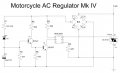
The voltage regulator that you need to add basically works as an automatic switch to ground. As soon as it “sees” a voltage of more than 14.5V to ground, it will start “shorting” the excess power. The standard AC regulator is connected parallel to the headlight, in between the power lead from the coil and the ground.

I normally recommend running a 50W headlight off of a 75W lighting coil together with an AC regulator. If you do a lot of low rpm riding (on difficult trails) you might even consider running a 35W headlight on the same 75W lighting coil. You will be amazed how much better it works!

Again: ensure that all connections you make are good. Twisting two wires together does not work, you will have to use proper crimp terminals or solder the wires. Taillights can be hooked up parallel to the headlight; the bulb normally doesn't exceed 5W.
 
Well i finally got this regulator pulled apart. This is what it looks like. let me know if i have something fundimentally wrong. Im not 100% sure i have the capacitor the right way around. When i was heating the resin mix, the skin on the capacitor was peeling off so i was lucky to be able to ID it as 100uf. Its was extremely hard to idenify some of the resistors and it felt like i was not going to have any luck with those as the coloured bands were comming off with the resin mix, but i reckon i did pretty well.


COMPONENT LIST

1 - Triac – PRX, SC151D – TO-220 case
2 - 6 pin chip – Motorola MOC3021, Q8637
3 - (T) Transistors – 2 of – Motorola BC 547, 7482F or 748ZF ? – TO-92 case
4 - (C) Electrolytic capacitor – 100uf, 10 volt (not 100% sure its 10V)

Resistors

R1 - Brown, Brown, Black, Red, Brown - 1/2W Metal film – 1%
R2 - Gold, red, red, red - 1/4W carbon film - 5%
R3 - Gold, Brown, Black, Brown - 1/4W carbon film - 5% - (Not 100% sure on the black& brown next to first brown)
R4 - Gold, Red, Purple, Red - 1/4W carbon film - 5%
R5 - Gold, Brown, Purple, Red - 1/4W carbon film - 5%
R6 - Gold, Black, Purple, Yellow – 1/4W carbon film - 5%

Diodes

D1, D2, D3, D4

Well I’m fairly sure they are just power diodes. The problem is I cant see any identification marks. No bands and no writing. If there was any then I would say its come off when I removed the potting mix which I had to heat up. I tried to be very careful, but I just couldn’t see any marks when digging away to reveal the these components. They measure approx 5mm long and 2.5mm OD. The wires are axially mounted, so one at each end, the case is a glossy black plastic and the wires are are little bit thicker than the resistor wires. That’s about all the info I can give about them but im sure they would be diodes but I have no idea of the values.

Component marked with a ? is the only other component I cant properly identify and it is a very tiny diode looking thing. It might be a zener but im really not sure. Its about the same diameter as the resisors but only about half to 3 quarters of the resistors length. Basically its extremely small and hard to handle. It actually broke in 2 bits so I removed it from the circuit. Its appears to be made of glass and it is a bright yellow colour with a wide black band at one end. I can see some code on it but its really hard to piece it all together. This is what I can see on it but im not sure the numbers/letters are in correct order

ZX
90
15
7

There looks like one other number but I cant really read what it is. Im thinking it might be a zener or at least a diode as it’s a glass item and the inside looks orangish.

Has anyone got this book or know where i can dowload a copy? ECG PHILIPS SEMICONDUCTORS MASTER REPLACEMENT GUIDE
I reckon i need that to ID the mystery diode.

Anyway, perhaps someone can draw up a good diagrame and then if we had identify everything properly then try and work out how it works and test it. I spent all afternoon on this so its taken a long time. I had to work out the circuit and draw it up in a way I could understand follow it.

On other thing, the only component directly contacting the negative/earth side of the bike is the mounting hole of the Triac. The wire I have shown at the top is the + wire that picks up the AC wire from the alternator. I imagine if we wanted to we could run a negative wire out of it too but I guess one wire to connect makes it simple.

There appears to be 2 legs on the Motorolla chip that are just soldered in but nothing connecting to them.

I can find datasheets on the Triac and Chip on the web easy enough.

So lets see how we go from here then
 
Last edited:

Thread Starter

Suzukiman

Joined May 1, 2010
94
Hi endoro250z, The BZX79C 15 is a 15 V 1/2W zener could that be the number?

I will put your diagram into a schematic and post it if you want.

You could just measure the resistors with a multimeter to be sure if the markings are correct. You can also check the diodes with the multimeter to find out which side is the cathode.
 
Last edited:
I dont think the resistor measurements would be accurate as i have had a lot of heat in the components when removing the resin and i think they will be heat affected and not give true measurements?

yes i think that the diode may be BZX but the C looks like a 0 but i will try looking at it with a magnifying glass again. For the capacitor you have 50 V but i know its more like 10 or 100 as i can see a 1 and zero.

Also there is no bridge rectifier, the diodes are individual and i think they may be 1N4004 ? Thats only a guess though as no numbers remain but i think they are a common sort of diode.

Another point is that this regulator failed after several years. I dont know what happened but it started blowing globes so it was replaced with a new one, so there may be a faulty component in it some where.

Also looks like we may have ID'd that mystery diode, do you reckon that the resistor linked to it drops the rating of the diode slightly? If not and it is runing at the full 15 volts as per zener spec that would explain why this make of regulator produces nice bright lights!

One other thing, this circuit can easily be constructed onto a small universal PCB. 5 rows of 13 holes/solder pads. Ive seen it in catalogues and the pads are close enough to be linked with solder.
 
Last edited:

Thread Starter

Suzukiman

Joined May 1, 2010
94
The rectifiers are just seperate diodes forming a bridge according to your diagram and would be 1N4004-7 I think. This is just to provide a DC voltage for the driver components of the triac.

I put the capacitor working voltage as 50 v just to be safe, 63 V should also be OK.

The zener could be 15 v or 7 V, not sure here untill you confirm the markings again.

I think the resistors should give you the proper measurements and you can just compare with the colours to varify. Can you confirm from which side the colours start, usually gold or silver is last but can have other colours as well. The first colour ring is usually closer to the edge as the last, but not always. Testing may help to varify.

The triac SC151D is a "non insulated" type and MT2 leg makes through to the mounting tab, thus to ground.

The MOC3912 chip is an optoisolated triac driver. The circuit drives a LED whith optically switches the internal triac connected to the SC151D gate and thus triggers it.
 
The zener wont be a 7 volt because this regulator was off a 12 volt bike so i reckon your right with 15 volts, but i was wondering if the 15 volts can be fine tuned with a resistor and perhaps making it work at 14.5 volts? I dont know what the designer of this circuit has done really.

i have written the resistor colours out in order next to gold/brown tollerance band.

So looking at the component specs, can you determine how much power this reg can shunt? is it solely determined by the Triac rating?

 
Last edited:

Thread Starter

Suzukiman

Joined May 1, 2010
94
The zener wont be a 7 volt because this regulator was off a 12 volt bike so i reckon your right with 15 volts, but i was wondering if the 15 volts can be fine tuned with a resistor and perhaps making it work at 14.5 volts? I dont know what the designer of this circuit has done really.

i have written the resistor colours out in order next to gold/brown tollerance band.

So looking at the component specs, can you determine how much power this reg can shunt? is it solely determined by the Triac rating?
Can you just varify if the zener markings look as if they could match BZX79C15 . I am not sure its 15V yet, as lower zener regulating voltages are also used so that if the voltage being sensed drops below the zener threshold than regulation will not work and in our case we want to regulate around 12V and not really 15V.

Jaycar in Oz has the datasheet for the triac and Google "MOC3021 data" and alldata has that one.
The last number 7 you saw bothers me a bit a 4.7 and a 7.5 zener is more commonly available, hopefully this is not part of the value number. 15V may actually be right if you can just double check that.

You can easily fine tune the triggering voltage by changing zeners or just adding a diode or two in series until you have the voltage you want or put two zeners in series to make up your voltage. Zeners usually are not exact and could vary by up to 5% (not sure here) so you have to actually select and test them. A 15V zener could be 15.75V or 14.25V and could cause bulbs to blow, normally they are lower.

Just to varify if you gave gold first and then the colour ring right next to it then I have the wrong values in as gold (or some other colours) is always the last (tolerance) value. I read your colours from the other side towards the gold. Let me know so I can fix that.
Edit: Only R5 could be affected 270 or 1K7 as per Murphys law.

Your Triac is 15A RMS current rated, normally its always best to go about double rating on such components. Thus I would say its good for 7 -10 Amps continuous use, but going higher may produce more heat etc. A BT138 or BT139 should also work and is also 15A.
 
Last edited:
Yep ok, i will try checking the resistors and zener.
The way i listed the resistors was first colour gold, then a gap then followed by the next 3 or 4 colours in order as they are on the resistor.

I will try looking at the zener again. If you saw what i had to work with you would see how difficult it is to read it off 2 broken bits that are tiny as. I can barely pick them up with tweezers!

Will get onto it later today/tonight.

Are their Triacs higher than 15 amps?
 

Thread Starter

Suzukiman

Joined May 1, 2010
94
Ok, it seems that I may have the resitor values on the schematic right then.
You can use a BTA140 which is rated at 25A.
I may do a quick improvemenet to the schematic and add the triacs in as well.
 

Thread Starter

Suzukiman

Joined May 1, 2010
94
Heres is the schematic as it stands now:
Hopefully someone with more electronics experience will be able to give us a detailled explanation on how it works or try it on a simulator.


Attachments

Last edited:
I haventy had time to do any resistor measuring tonight. My multi meter is also a bit dodgy aswell. Gotta start looking for a decent new one. Where do you find the BZX zener codes? i looked all over and couldnt find them.

I also wonder if using a 1N5352B would be beneficial? (5W rating, perhaps a bit beefier/sturdy?)

I looked in my stuff and found a brand new MSR/Moose 12v AC reg (made by Tympanium Corp USA) They are the ones in an alloy case with a stud mount hole. I can actually see the back side of the ciruit board inside. I can see there is a chip, some sort of TO-220 device and some other componants. I dont want to open this one up though. What i think i will do is buy a brand new one rated at 225watts and open it up and see how similar the design is to the latest one we have got. These regs came in 2 ratings. 225W and something lower. I will get a 225W and then see the specs for the components. it should be easy to get into because the resin is soft.

I also had a thought If the triac is rated 15amps, and zener 15v that means 15 x 15 = 225watts! I think its gonna be interesting to see what the Tympanium regs use for their Triac/trans to get the 225W rating.

I reckon i personally would stick with the 15 V zener. It doesnt blow globes and they are quite bright at 15 V. Since there is no diode linked to the zener in our circuit that would mean that its running at 15V then. I thought the resistor linked to it above could have been dropping it. I still want to try and double check the zener code, but it will be tricky.
i wouldnt be surprised if many of the aftermarket regulators work at 15volts anyway.

I noticed you shifted the position of the capacitor on the circuit drawing. Any reason?

This would work on bikes that have over 30 volts unregulated AC aswell. I have seen some specs for some Yamaha and suzuki trail bikes making about 35-40 volts AC.

With the other Triacs, could we just fit one of those and still keep the same Triac driver?
 
Last edited:

Thread Starter

Suzukiman

Joined May 1, 2010
94
As you start typing bzx in Google it will start listing i.e bzx55c. bzx83C, bzx84C, bzx79C etc, just select one and then I always choose "Alldatasheet" and get the PDF to open with the list and specs.

The Zener does not have to be high current type, 1/2W will do, it only provided the reference voltage to the first transistor and the current is limited by the resistors in series with it. I think there is less than 10mA going through it in the schematic.

If a triac rating at 15 volts is 15A = 225 watts, it would not be a good idea to run a semiconductor at its maximum rated capacity, especially continuously. If you need to regulate 225 watts then you should go for a triac of 30A to be safe and keep heat down. We must also not forget that the current to the load will not be passed through the triac, just the excess voltage. So the more used by the load the less "current" through the triac toground. A 12A or maybe 8A would most likely be more than sufficient.

Many bikes have a Rectifier/regulator that regulates at 14.2 to 15V, but then we have a battery as a damping factor there and fluctuations are not a big problem.

Yes it would regulate with much higher voltage. Aagin many bikes with 3 phase R/r's push up to 80V AC out on each phase which is then rectified and regulated for charging a 12 volt battery.

I think that fitting the BTA140 25 Amp should work the same, although I have not checked any specs as I am not too familiar with these components. One should just compare the gate requirements on the spec sheets.

I think in some they could be using a 8A rated component for rgulating less than 120Wmaybe these are used on the Honda XL 250 as only the 35 headlamp bulb is run on AC.
The Hond XR650 (The Big Red Pig) has a finned one under the seat which I think will have a higher capacity.

The beauty about knowing whats inside them makes it repairable, meaning one could just replace all the components and not bother with carefull opening and just reuse the case or you could assemble your own. The weak part is usually the capacitor which dries out over time and may take a component with it, so its always a good idea to replace the cap, maybe even with a higher working voltage type.

If you go right back to post #10 solcar gave a diac regulator with 15V zeners to try. I have it laying in front of me and I used a BT138 12A triac, but unfortunately that configuration did not work.

Anyway good job you did so far, please keep me in the loop with further developments. I hope some of the wise men on the forum is going to have a look at the schematic and give us some feedback.
 
Last edited:

Norfindel

Joined Mar 6, 2008
326
Seeing the circuit, it looks like the idea is to short-circuit the AC for the whole remaining of the cycle, if the voltage goes above about 16v.

Not sure if that 100uF capacitor is accurate. Difficult to tell without simulating, but 100uF shunted by a 2k7 resistor would take some time to discharge, and i think it would probably keep the Triac triggered forever.

Also, i don't see why someone would want to shunt the AC for the whole remaining of the cycle. It seems to me like it's easier to rectify it, and use a zener and emitter-follower, and would result in better regulation.
 

Thread Starter

Suzukiman

Joined May 1, 2010
94
I hope to get back to this on the weekend.
No problem, waiting for you as you are the main source of info now to confirm that the schematic is drawn exactly right!
Hope you can build a pilot one for testing, I will have to order the parts, but do not have a bike at hand for testing.
Can you give a picture of the component board please.
Thanks
 
Ok, I tried to measure the resistors. I had about 4 multimeters and all were dodgy enough in one way or another. Crappy leads, which caused a loss of continuity, flat batteries, broken leads etc etc. Kept getting some reading ‘OL’ all the time. Its made me crazy. No more cheap multimeters from Jaycar! I just want to get a real decent one for under $200 USD. I think I will get a Fluke as I recognise them as being good but I have no idea what model.

Anyway I found a digital ‘Digitech’ one that seemed to work but had iffy mis-matched leads with poor connectors so I tried to use that.

A re-cap. This is what I had below. First colour is tolerance band, then there was a bit of a gap, then the coloured bands. Let me point out, when I started I had zero faith in the reliability and accurateness of the meter I was using, The resistors had been severely heat affected from my heat gun from removing the circuit board, so the resistors could be damaged, the resistors were still in the circuit board and I may have got some iffy measurements going through some poor solder connections. Multimeter overall condition was questionable and I wasn’t really sure the readings I got were going to be accurate!

Also I was getting a little variation while holding the probes, but I tried to take a measurement after waiting a little for meter to find resting point. Eg one may have measured around 266.6 – 270.20

R1 – Brown - Brown, Black, Red, Brown - 1/2W Metal film – 1%
For R1 I was getting 1.202 on KOhm scale. For some reason I could not get a reading on plain Ohm scale. Kept on saying OL. Also looking at this resistpr, there is a slight chance it may be Brown - Brown, Black, Brown, Brown. The second to last colour maybe a brown, but I think it’s a red and is just a little burnt looking from heat. Can you check your calulations as you had 120 Ohms but I kept measuring 1.202 KOhms.

R2 – Gold – red, red, red - 1/4W carbon film - 5%
For R2 I was getting 2.245 on KOhm scale. (was also getting 2.239 KOhms at one stage)

R3 – Gold - Brown, Black, Brown - 1/4W carbon film - 5% - (Not 100% sure on the black, brown next to first brown)
For R3 I was getting 102.2 on Ohm scale.

R4 – Gold - Red, Purple, Red - 1/4W carbon film - 5%
For R4 I was getting 2.699 on KOhm scale.

R5 – Gold - Brown, Purple, Red - 1/4W carbon film - 5%
For R5 I was getting 267.4 on Ohm scale. (few times was getting 266.7 Ohms)

R6 – Gold - Black, Purple, Yellow – 1/4W carbon film - 5%
For R6 I was getting 47.3 on Ohm scale. Can you recheck this one as it doesn’t seem to match what you got. You had 470 Ohms but I had 47.3 Ohms????

Well, I think I did a good job at that considering the meter I had to work with.

Next I gotta have look at the zener again. Also is there a test I can do for the diodes in the circuit? Do we need to do this? Can we find a value for them? Theres no writing remaining remember. I’m not sure how critical it is.

I re-checked the capacitor. Its definitely on the otherside of R4 like in your first drawing. I’m 100% on 100uf and 99% sure on 10volts but if you guys reckon 63volts is the way to go then I’m happy with that.

The last grey area is the transistors. Although my reading of BC547 is correct, in one of my old Dick Smith electronics catalogues lists several spec BC547 but the Jaycar book only lists one. I’m not sure how critical it is.
 
Last edited:
Status
Not open for further replies.
Top