Facebook
 Google
 GitHub
 Linkedin
Hello;
I just happened across this forum and the thread I posted the link to below, so I thought someone here might be able to help me. I am completely clueless about how regulators and rectifiers, and diodes, and transistors etc work, so if possible, explaining things at a grade school level or below would be helpful, lol.
I have a 1974 Kawasaki 90, with a 6 volt battery system and it uses points instead of electronic ignition.
https://forum.allaboutcircuits.com/threads/how-to-build-a-6v-ac-regulator.150244/
These are quotes from the link above and one of them may be what my stock system uses.
"Some light weight Japanese motorcycles used a bidirectional AC Zener shunt regulator, but the cheapo AC lighting system probably didn't continue on more recent models - and service spares "black box" units tend to be a bit pricey."
"Most small motorcycles just had a ballast resistor for when only running lights (a few had posh AC Zeners as I mentioned in an earlier post) its pretty much balanced to the PTC characteristics of correctly rated bulbs."
The headlight and engine are run off the stator, and the tail light, brake light, turn signals are run off the battery.
The battery has 6.1 - 6.2 volts with the key off.
The maximum voltage the charging system reaches (with the engine running at around 1800 rpm and above) is 6.0 with the lights off, and It only reaches around 5.85 with the headlight and tail light on. The voltage "cycles" or varies on my cheapo $7.00 voltmeter from a low of around 2.5 volts up to the peak voltages of 5.85 or 6.0, meaning it is not a steady 6.0 with the headlight off or 5.85 with the headlight and tail light on.
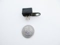
It has a 2 wire regulator or rectifier that is only 1" long x 3/8" wide x 1/2" deep in size which may ground to the frame, so my thinking is that if they can regulate the voltage to the battery with something that small, it shouldn't be very complicated or difficult to make one of these units, but I certainly could be very wrong.
I checked the charging system with both the original regulator and a new one and it read the same voltage, so it seems that both regulators are good.
While it was running, I unplugged the 2 wire plug that goes to the regulator and checked the voltage coming from the staor. It was around 5 volts at idle and went up to around 10 volts at around 1800 rpm and didn't go much higher with more rpm, so it seems the stator is good.
If possible, I want to have around 6.2 - 6.5 volts going into the battery with the headlights on while riding using the same type of system/regulator it currently has so I can keep the wiring stock. My guess is that this will give me around 6.17 - 6.75 volts to the battery with the lights off, and this should be enough to keep my battery from slowly draining while I ride it. It's ok if it puts out slightly less voltage at idle.
The bike is completely stock, so I have no idea why the regulator isn't putting out a little more voltage to the battery, unless, the stator is a little weak (which I doubt) and that if it put out more voltage, the regulator would put out more as well unless it is fixed somehow to only put out a maximum of around 6.02 volts.
Also, since the battery voltage drops slightly when the engine is running, and drops even more when the headlight and tail light are on, it seems that they are robbing enough power from the stator that it can't put out more than 6.02 volts after the regulator even though the stator sends 10 volts to the regulator when the engine is running.
I'm sooo, confused, lol.
Any help is greatly appreciated.
I just happened across this forum and the thread I posted the link to below, so I thought someone here might be able to help me. I am completely clueless about how regulators and rectifiers, and diodes, and transistors etc work, so if possible, explaining things at a grade school level or below would be helpful, lol.
I have a 1974 Kawasaki 90, with a 6 volt battery system and it uses points instead of electronic ignition.
https://forum.allaboutcircuits.com/threads/how-to-build-a-6v-ac-regulator.150244/
These are quotes from the link above and one of them may be what my stock system uses.
"Some light weight Japanese motorcycles used a bidirectional AC Zener shunt regulator, but the cheapo AC lighting system probably didn't continue on more recent models - and service spares "black box" units tend to be a bit pricey."
"Most small motorcycles just had a ballast resistor for when only running lights (a few had posh AC Zeners as I mentioned in an earlier post) its pretty much balanced to the PTC characteristics of correctly rated bulbs."
The headlight and engine are run off the stator, and the tail light, brake light, turn signals are run off the battery.
The battery has 6.1 - 6.2 volts with the key off.
The maximum voltage the charging system reaches (with the engine running at around 1800 rpm and above) is 6.0 with the lights off, and It only reaches around 5.85 with the headlight and tail light on. The voltage "cycles" or varies on my cheapo $7.00 voltmeter from a low of around 2.5 volts up to the peak voltages of 5.85 or 6.0, meaning it is not a steady 6.0 with the headlight off or 5.85 with the headlight and tail light on.
It has a 2 wire regulator or rectifier that is only 1" long x 3/8" wide x 1/2" deep in size which may ground to the frame, so my thinking is that if they can regulate the voltage to the battery with something that small, it shouldn't be very complicated or difficult to make one of these units, but I certainly could be very wrong.
I checked the charging system with both the original regulator and a new one and it read the same voltage, so it seems that both regulators are good.
While it was running, I unplugged the 2 wire plug that goes to the regulator and checked the voltage coming from the staor. It was around 5 volts at idle and went up to around 10 volts at around 1800 rpm and didn't go much higher with more rpm, so it seems the stator is good.
If possible, I want to have around 6.2 - 6.5 volts going into the battery with the headlights on while riding using the same type of system/regulator it currently has so I can keep the wiring stock. My guess is that this will give me around 6.17 - 6.75 volts to the battery with the lights off, and this should be enough to keep my battery from slowly draining while I ride it. It's ok if it puts out slightly less voltage at idle.
The bike is completely stock, so I have no idea why the regulator isn't putting out a little more voltage to the battery, unless, the stator is a little weak (which I doubt) and that if it put out more voltage, the regulator would put out more as well unless it is fixed somehow to only put out a maximum of around 6.02 volts.
Also, since the battery voltage drops slightly when the engine is running, and drops even more when the headlight and tail light are on, it seems that they are robbing enough power from the stator that it can't put out more than 6.02 volts after the regulator even though the stator sends 10 volts to the regulator when the engine is running.
I'm sooo, confused, lol.
Any help is greatly appreciated.