 Facebook
 Google
 GitHub
 Linkedin
Yes, the supply that came with the car had the charger circuitry in it. That's why an AGM charger would be best.Actually the charger that came with the car had a light which turns on red while charging and once it's fully charged it turns green. Even if I plug the charger pin to the car without inserting to the wall socket it would turn green as it gives currency out from the car as well.
12v 7ah battery charger
- Thread starter rbwadhar
- Start date
Scroll to continue with content
It's difficult to get that type of charger here so I guess I will just use a normal 14v or 15v adaptor with a 2ah max output and keep the car on charging for maximum 3 hours one go so as not to damage the battery. Is that correct way to use?Yes, the supply that came with the car had the charger circuitry in it. That's why an AGM charger would be best.
DC power supplies have an rating in amps (A) not amp hours (Ah) which is a battery specification. A 2A supply for 3 hours seems safe.It's difficult to get that type of charger here so I guess I will just use a normal 14v or 15v adaptor with a 2ah max output and keep the car on charging for maximum 3 hours one go so as not to damage the battery. Is that correct way to use?
Ok. So if I get a 2a adaptor then can charge for 3 hours and if it's less like 1.5a or 1a how many hours can I keep the battery on charging for one go so it doesn't get damage.DC power supplies have an rating in amps (A) not amp hours (Ah) which is a battery specification. A 2A supply for 3 hours seems safe.
I can't really tell you that. If I was doing this and couldn't get a charger, I would monitor the current and voltage. It's a guess.Ok. So if I get a 2a adaptor then can charge for 3 hours and if it's less like 1.5a or 1a how many hours can I keep the battery on charging for one go so it doesn't get damage.
You need to know if the adaptor will limit the current, since a battery is a very low impedance and will look like a short to the adapter.So if I get a 2a adaptor then can charge for 3 hours and if it's less like 1.5a or 1a
You may need to add a small resistance in series to limit the current to a safe level, if the adapter doesn't do that.
Last edited:
As you now know from the other posts that you need an adapter that can put out maybe around 14 or 15 volts DC. The bulk charge voltage for a typical sealed lead acid (SLA) is around 14.8 but could be lower depending on temperature.Ok. So if I get a 2a adaptor then can charge for 3 hours and if it's less like 1.5a or 1a how many hours can I keep the battery on charging for one go so it doesn't get damage.
There are two basic types of wall warts around these days too.
1. Unregulated (old style).
2. Regulated (new style most common today).
The regulated type usually put out a voltage very close to their rating. So if you buy a 12vdc unit it will put out very close to 12vdc and stay at that voltage for the most part unless overloaded.
The unregulated older type putout an average 12vdc but the peaks will be higher. In the old days, these were ideal for charging lead acid batteries because the peaks would pulse charge the battery and that was believed to be the best way, at least back then. So if you get one of these it would probably work or you could just go a bit higher like around 14vdc.
The modern chargers however, even the small ones, have a 4 or 5 stage charging profile that charge the battery in the best possible way and terminate when the battery is 'full' and then float charge the battery indefinitely. Float charging is considered non damaging as it just keeps the self discharge from discharging the battery when it is not under load.
So first choice is the modern charger. Maybe you could get someone to buy you one and mail it to you . I dont know what the exchange rate is anymore or if you have Paypal maybe then you can arrange something with someone.
Second choice is either the unregulated or the regulated. The idea of the series resistor is a good one too as talked about here already. When you place a series resistor in series with the wall wart you effectively lower the current that gets to the battery and at the same time provide a gradual tapering off of the charging current.
The resistor is selected based on the max charging current for a given battery but you can go with less current and still have the battery charge someone properly. For example if you have a 15v wall wart and the battery is at 12v and the resistor is 1 Ohm, then the current is (15-12)/1=3 amps. That might be a bit high for your battery though, maybe 1 amp would be better. That would mean a 3 Ohm resistor would be required. As the battery charges however, the voltage rises so the current decreases. As the battery voltage rises to 13v with a 1 Ohm resistor the current would be (15-13)/1=2 amps, so you see it starts to come within the required current already. Sometimes it doesnt take long to reach that voltage either but other times it will so you might want a couple different value resistors. Be aware though that the power rating of the resistor also has to be right. The power is:
P=R*I*I
with R the resistance in Ohms and I the current in amperes and P in watts, and it is best to choose a resistor that is at least two times better than that calculation or:
P=2*R*I*I
which means you get a resistor with a larger power rating than the actual power will be.
There is another choice, and that is a bench power supply. With a bench power supply you can adjust the voltage as needed while monitoring the current. You can then set the current to be whatever is required and change it later as the voltage of the battery rises. This works pretty well. I actually did this using a 30vdc 10 amp max power supply for a number of years. You can also use a series resistor to soften the voltage coming out of the power supply.
So now we come to the question of just how long do we charge the battery for given a known capacity rating of the battery. The 'ideal' time is:
t=AhrRating/Current
which is the ampere hour rating divided by the charge current. So if the ampere hour rating is 7 ampere hours and the current is 1 amp, it would take 'ideally' 7 hours to charge. This is the ideal scenario where we have an ideal battery and constant current. Of course in real life we dont have an ideal battery so we have to make adjustments.
The first adjustment is for the charge efficiency. The charge efficiency can be as low as 50 percent for a lead acid battery and that would mean double the charge time. If the charge efficiency of your battery is 75 percent, then you only need around 1.5 times the ideal charge time.
Now as to over charging, if you charge too long you lessen the battery life. If you keep the current going for too long that could ruin the battery. If you keep the voltage of the power supply at around 13.8 after a time though it will just keep the battery charged but not charge it anymore (at around 20 degrees C that is).
So you can see the charge time is a little bit of a guess because we dont know the charge efficiency for certain. One way around this is to charge with an assumed efficiency of maybe around 80 percent and then see how long the battery lasts, or better yet, test the battery for it's ampere hour output once you believe it is fully charged. If the battery reads low, then increase the charge time.
Lead acid batteries only have cycle life of around 300 to 500 at best so eventually you have to buy a new one. The newer LiFePo4 batteries have a cycle life of 1000 to 2000 which is much better, but you have to be more careful with them and you have to make sure the battery you buy is rated for the max current needed in the application. Lead acid batteries have a jump here because they can put out quite a hefty current in most cases while LiFePo4 batteries have to be made specifically for higher currents to be used for high current applications. It is very tempting to get one because for the eact same size as the 7 ampere hour SLA battery you could get a 10 ampere hour LiFePo4.
Regardless what you do though, be sure not to accidentally reverse the charger leads. That could blow the wall wart or charger or bench power supply if they are not protected. The current in that case goes way up and can really ruin equipment fast. One way is to use red and black leads and if needed paint somewhere around the terminals red for positive and black for negative, or just label them clearly. One mistake and it might take you weeks to get new equipment.
With my many years of experience in the power control industry i still managed to do this one time and blew out my 150 dollar (USD) power supply. Lucky i can fix that stuff too. It was a shock though. I was half asleep and reversed the leads, and something inside popped and smoked. The power supply had to be fixed, and i added a protection circuit so it would not happen again even if i reversed the leads again. I was lucky too that the damage was not too severe, but it could have been much much worse. I have seen expensive power supplies with transistors that cost 100 dollars (USD) each (and had 4 to 6 of them in the unit) blow out. The repair cost for the parts alone is nuts.
I hope this helped a little although i know it is a little more complicated than you probably would like to see. That is the world of charging batteries for ya though. Good luck with it
")
Last edited:
Ok. Can you show me how to monitor it then. And what things do I need for it.I can't really tell you that. If I was doing this and couldn't get a charger, I would monitor the current and voltage. It's a guess.
Thanks a lot for the info.As you now know from the other posts that you need an adapter that can put out maybe around 14 or 15 volts DC. The bulk charge voltage for a typical sealed lead acid (SLA) is around 14.8 but could be lower depending on temperature.
There are two basic types of wall warts around these days too.
1. Unregulated (old style).
2. Regulated (new style most common today).
The regulated type usually put out a voltage very close to their rating. So if you buy a 12vdc unit it will put out very close to 12vdc and stay at that voltage for the most part unless overloaded.
The unregulated older type putout an average 12vdc but the peaks will be higher. In the old days, these were ideal for charging lead acid batteries because the peaks would pulse charge the battery and that was believed to be the best way, at least back then. So if you get one of these it would probably work or you could just go a bit higher like around 14vdc.
The modern chargers however, even the small ones, have a 4 or 5 stage charging profile that charge the battery in the best possible way and terminate when the battery is 'full' and then float charge the battery indefinitely. Float charging is considered non damaging as it just keeps the self discharge from discharging the battery when it is not under load.
So first choice is the modern charger. Maybe you could get someone to buy you one and mail it to you . I dont know what the exchange rate is anymore or if you have Paypal maybe then you can arrange something with someone.
Second choice is either the unregulated or the regulated. The idea of the series resistor is a good one too as talked about here already. When you place a series resistor in series with the wall wart you effectively lower the current that gets to the battery and at the same time provide a gradual tapering off of the charging current.
The resistor is selected based on the max charging current for a given battery but you can go with less current and still have the battery charge someone properly. For example if you have a 15v wall wart and the battery is at 12v and the resistor is 1 Ohm, then the current is (15-12)/1=3 amps. That might be a bit high for your battery though, maybe 1 amp would be better. That would mean a 3 Ohm resistor would be required. As the battery charges however, the voltage rises so the current decreases. As the battery voltage rises to 13v with a 1 Ohm resistor the current would be (15-13)/1=2 amps, so you see it starts to come within the required current already. Sometimes it doesnt take long to reach that voltage either but other times it will so you might want a couple different value resistors. Be aware though that the power rating of the resistor also has to be right. The power is:
P=R*I*I
with R the resistance in Ohms and I the current in amperes and P in watts, and it is best to choose a resistor that is at least two times better than that calculation or:
P=2*R*I*I
which means you get a resistor with a larger power rating than the actual power will be.
There is another choice, and that is a bench power supply. With a bench power supply you can adjust the voltage as needed while monitoring the current. You can then set the current to be whatever is required and change it later as the voltage of the battery rises. This works pretty well. I actually did this using a 30vdc 10 amp max power supply for a number of years. You can also use a series resistor to soften the voltage coming out of the power supply.
So now we come to the question of just how long do we charge the battery for given a known capacity rating of the battery. The 'ideal' time is:
t=AhrRating/Current
which is the ampere hour rating divided by the charge current. So if the ampere hour rating is 7 ampere hours and the current is 1 amp, it would take 'ideally' 7 hours to charge. This is the ideal scenario where we have an ideal battery and constant current. Of course in real life we dont have an ideal battery so we have to make adjustments.
The first adjustment is for the charge efficiency. The charge efficiency can be as low as 50 percent for a lead acid battery and that would mean double the charge time. If the charge efficiency of your battery is 75 percent, then you only need around 1.5 times the ideal charge time.
Now as to over charging, if you charge too long you lessen the battery life. If you keep the current going for too long that could ruin the battery. If you keep the voltage of the power supply at around 13.8 after a time though it will just keep the battery charged but not charge it anymore (at around 20 degrees C that is).
So you can see the charge time is a little bit of a guess because we dont know the charge efficiency for certain. One way around this is to charge with an assumed efficiency of maybe around 80 percent and then see how long the battery lasts, or better yet, test the battery for it's ampere hour output once you believe it is fully charged. If the battery reads low, then increase the charge time.
Lead acid batteries only have cycle life of around 300 to 500 at best so eventually you have to buy a new one. The newer LiFePo4 batteries have a cycle life of 1000 to 2000 which is much better, but you have to be more careful with them and you have to make sure the battery you buy is rated for the max current needed in the application. Lead acid batteries have a jump here because they can put out quite a hefty current in most cases while LiFePo4 batteries have to be made specifically for higher currents to be used for high current applications. It is very tempting to get one because for the eact same size as the 7 ampere hour SLA battery you could get a 10 ampere hour LiFePo4.
Regardless what you do though, be sure not to accidentally reverse the charger leads. That could blow the wall wart or charger or bench power supply if they are not protected. The current in that case goes way up and can really ruin equipment fast. One way is to use red and black leads and if needed paint somewhere around the terminals red for positive and black for negative, or just label them clearly. One mistake and it might take you weeks to get new equipment.
With my many years of experience in the power control industry i still managed to do this one time and blew out my 150 dollar (USD) power supply. Lucky i can fix that stuff too. It was a shock though. I was half asleep and reversed the leads, and something inside popped and smoked. The power supply had to be fixed, and i added a protection circuit so it would not happen again even if i reversed the leads again. I was lucky too that the damage was not too severe, but it could have been much much worse. I have seen expensive power supplies with transistors that cost 100 dollars (USD) each (and had 4 to 6 of them in the unit) blow out. The repair cost for the parts alone is nuts.
I hope this helped a little although i know it is a little more complicated than you probably would like to see. That is the world of charging batteries for ya though. Good luck with it
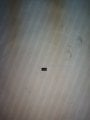
I found a small stuff which was connected to the power input of the adaptor and the red wire connecting to the battery. Check the attached photo as it got broken from the connection and I don't know what it's called and it's specs to get a new one. It looks like a small plastic with both side having wire to connect.

Attachments
-
 1.7 MB Views: 9
Last edited by a moderator:
That looks like a diode. Does it have any markings on it?Ok. Can you show me how to monitor it then. And what things do I need for it.
Thanks a lot for the info.
I found a small stuff which was connected to the power input of the adaptor and the red wire connecting to the battery. Check the attached photo as it got broken from the connection and I don't know what it's called and it's specs to get a new one. It looks like a small plastic with both side having wire to connect.
It written R 2C 7That looks like a diode. Does it have any markings on it?
M1C
It's not very clear to read as the fonts have been rubbed away a bit. So I'm not sure if it's the correct stuff written on it
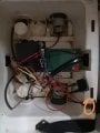
It was connected after the adaptor plug with the red wire going to the battery. See the attached photo as I have marked a circle and connected the red wire directly to the charging port.Where exactly was it?
Attachments
-
 1.9 MB Views: 8
It’s a diode. It’s to prevent the battery from discharging into the charger and possibly to prevent reverse polarization. It looks underrated for its application but I would replace it with a 1N5404 3A rectifier diode.
It will have a white band on one end that will face the battery. If you get it backwards it just won’t work In which case you just have to flip it around.
It will have a white band on one end that will face the battery. If you get it backwards it just won’t work In which case you just have to flip it around.
Is it a must that I have to place it. Can't I connect the wire directly. Cues I will remove the adaptor plug from the car once I finish charging. So it won't give the current back to the adaptor.It’s a diode. It’s to prevent the battery from discharging into the charger and possibly to prevent reverse polarization. It looks underrated for its application but I would replace it with a 1N5404 3A rectifier diode.
It will have a white band on one end that will face the battery. If you get it backwards it just won’t work In which case you just have to flip it around.
I have no knowledge about what might be available in Sudan, but I find it hard to believe you cannot purchase a 12v battery charger. You're trying to use power adapters as Chargers and this is unlikely to work. Otherwise your risking damage to your equipment or spending lots of time and money custom building a charger when you can just buy one.
If you have a car, truck or tractor and it has a battery, find someone who has a battery charger for those.
If you have a car, truck or tractor and it has a battery, find someone who has a battery charger for those.
Very often car battery chargers are not suitable for SLA batteries because they rely on the battery impedance as well as the voltage. They could easily overcharge the SLA battery.I have no knowledge about what might be available in Sudan, but I find it hard to believe you cannot purchase a 12v battery charger. You're trying to use power adapters as Chargers and this is unlikely to work. Otherwise your risking damage to your equipment or spending lots of time and money custom building a charger when you can just buy one.
If you have a car, truck or tractor and it has a battery, find someone who has a battery charger for those.
The right way is as you say get a recommended SLA charger.
I was going to say take more pictures of that thing on the sides, top, bottom, and place a ruler in the picture so we can get a feel for the dimensions.Ok. Can you show me how to monitor it then. And what things do I need for it.
Thanks a lot for the info.
I found a small stuff which was connected to the power input of the adaptor and the red wire connecting to the battery. Check the attached photo as it got broken from the connection and I don't know what it's called and it's specs to get a new one. It looks like a small plastic with both side having wire to connect.
View attachment 236826
If you have already determined it's a diode that's ok though just thought i would double check.
That is very observant of you. A series diode can not protect against reverse polarity because the diode has to point in the direction of current flow in a non reverse situation and it just so happens that is the right direction for current flow when the polarity is reversed too.No, reverse polarity protection in parallel with the input.
And yes, we have to connect a diode in reverse parallel in order to shunt the current away from the power supply when there is a reverse polarity connection of another voltage source.
That, combined with an appropriately rated fuse, is the key to protecting the power supply. When the protection diode conducts, the blows the inline fuse and thus disconnects the second source of power that would have otherwise blown the power supply.
That's exactly how i protected one of my big power supplies. It originally had a reverse protection diode but no fuse inline so the diode blew out but lucky it blew short so it kept the input shorted. I think there is a chance that it could have blown open with enough external current so an inline fuse is really necessary. The downside of the fuse is that it has a certain resistance, and low as it may be, it will still interfere with the voltage regulation of the supply under load. This means that the voltage sense line should be connected to the other side of the fuse so that the control circuit will be controlling the very output not the output before the fuse. I did not do that with my supply yet but i did use the diode and fuse. Unfortunately there was no room inside the case for the extra fuse and i wanted the diode mounted so that it could be accessed more easily (it was buried deep in the case so the circuit board had to be pulled to get to the diode originally) so i mounted the fuse and diode outside of the case. Looks very strange like that but provides really good protection.
But if there is enough current available, they will then open.Usually diodes fail short.


