6/12/24v 300a battery charger

Thread Starter

BrokeAgain

Joined Jan 15, 2026
12
Hoping for some help and, maybe, a miracle.

First, a lil backstory for context. I have a small hobby shop and the kids in the neighborhood bring their projects over where they can use my space and tools and I help them along. Just trying to pay forward a kindness shown to me in my misspent youth.

I came home the other day to my battery charger disassembled surrounded by 3 kids scratching their heads. It worked last time I used it, but they said they couldn't get it to work and tried to surprise me by fixing it themselves.

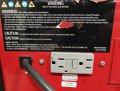
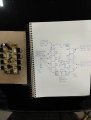
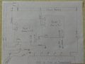
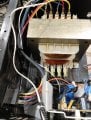
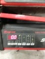
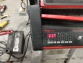
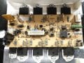
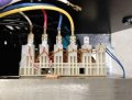
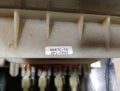
It's a Snap-on eebc-500. I can't find any data sheets or wiring schematics beyond a simple PDF owner's manual. I do know the transformer is a Schumacher part# 0093026670 and the rectifier/heatsink assembly is Schumacher part# 2299001769. Both of which are discontinued/obsolete.

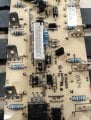
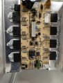
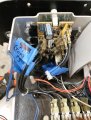
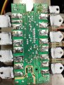
I can see a diode that's been burnt in the middle of the board. No clue of its specs, but if you guys can ID it, I can replace it.

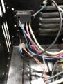
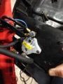
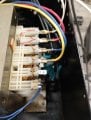
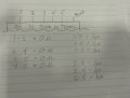
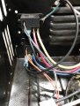
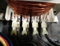
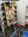
Next is the wiring. The kids pulled wires without labeling them. Fairly certain, the AC in on the transformer is controlled by two relays that are switched by the Orange and Gray wires from the middle of the board and power different windings according to DCV out requested at control panel. Could be completely wrong, though.

My diag tools are limited to a couple of DMMs and test lights.

Any and all help is appreciated

I have attached all of the relevant photos I could think of. If more are needed, I'm happy to oblige. Thanks in advance
 

Attachments

gaber2611

Joined Mar 14, 2013
321
First, could you rearrange the wiring for the charger in right manner, after the guys repair trial?
If you sure that every wire in its place, then you may send us the nameplate photo of the charger, so we try find the burnt diode specs.
For now confirm that the wires are connected correct
 

Thread Starter

BrokeAgain

Joined Jan 15, 2026
12
First, could you rearrange the wiring for the charger in right manner, after the guys repair trial?
If you sure that every wire in its place, then you may send us the nameplate photo of the charger, so we try find the burnt diode specs.
For now confirm that the wires are connected correct
Here is the only "faceplate" on the charger. Located on the back. I am not sure of the wire locations on the transformer or the control board as they were mostly removed when I found them staring at it. I'm including a pic of my best guess based on continuity list included in original post pics. As stated, it is a snap-on model= eebc-500 and is manufactured by Schumacher. I have provided the part numbers for the control board and transformer above. Was hoping someone could look at the transformer and tell me where the AC wires go. Also where the wires go by deducing the logic of the control board. I'm fairly certain the orange control wires coming from the bottom relay pictured are positioned in the wrong place on the board as beneath the connector on the board is printed "fan 1". Thinking, maybe it goes in the opposite corner where it's printed "B1 as" ? Blue wires could be in wrong position, as well. Printed on board beneath the connector is "Pr1-con"
 

Attachments

Well, you're kind of in a pickle. But your good pictures and drawings help a lot.

Schumacher is the OEM for many companies' battery charger products. So the Snap-on EEBC-500 would be made by them, as a custom unit.
I've drawn a few schematics for Schumacher chargers. It's unfortunate they don't provide them and constantly obsolete the boards when a small repair is all that is needed. But it's hard to stare at pictures. I don't know this particular model.

There is a small aux transformer winding (the two small blue wires) that powers the display board.
The cooked diode is a vanilla rectifier for the input to the 6VDC voltage regulator power for the front panel board. (IC L7806CV on heatsink).
So a suitable replacement would be a 1N4007, or UF4007. Nothing too special- but let's put in a high voltage part that will take the power surges and spikes lol. This is also from another picture of the board. Note it was only sold as the entire assembly 2999001769.
Don't put the new diode in backwards, pay attention to the stripe on the end, pointing same as the diode next to it.

I would have to look later at the pics for the transformer wiring. Will try later. Where is the fan connector?
 

Thread Starter

BrokeAgain

Joined Jan 15, 2026
12
Well, you're kind of in a pickle. But your good pictures and drawings help a lot.

Schumacher is the OEM for many companies' battery charger products. So the Snap-on EEBC-500 would be made by them, as a custom unit.
I've drawn a few schematics for Schumacher chargers. It's unfortunate they don't provide them and constantly obsolete the boards when a small repair is all that is needed. But it's hard to stare at pictures. I don't know this particular model.

There is a small aux transformer winding (the two small blue wires) that powers the display board.
The cooked diode is a vanilla rectifier for the input to the 6VDC voltage regulator power for the front panel board. (IC L7806CV on heatsink).
So a suitable replacement would be a 1N4007, or UF4007. Nothing too special- but let's put in a high voltage part that will take the power surges and spikes lol. This is also from another picture of the board. Note it was only sold as the entire assembly 2999001769.
Don't put the new diode in backwards, pay attention to the stripe on the end, pointing same as the diode next to it.

I would have to look later at the pics for the transformer wiring. Will try later. Where is the fan connector?
I have pulled both fans and set them aside for less wiring confusion. I seriously appreciate all the help. So, the blue DC wires from front side of transformer get plugged in where? Pri-con? B1as?

Trying to look at the relays, logically, it seems the 110v power sequence to the transformer would go yellow to red and then to blue controlled by the Orange and Gray wires coming from the board. Would it be beneficial to bypass the relays and connect mains directly to different legs of the transformer and note DC output on the other side? Or, could that damage the transformer?
 
OK did up a PC board schematic, and the roasted diode is _not_ for the 6VDC display board power like I thought.
The blue connector should not go to the "Pri-con" header like in your pic. This would make the diode smoke. It should go to "B1as".
The grey connector to "JMP" is OK. "Relay_6" is the name for the nearby jumper.
The orange connector to the FAN1 header? Nyahhh I would put it at "Pri-con" for the second relay.

Tomorrow I can do the transformer figuring out and narrow it all down.
Can you tell me where incoming mains "hot" goes to? I think it would (eventuially) go to your transformer pin 1 on the AC in side. The transformer thermal fuse is across 1-2.
Just have to figure out the tap changing relays.
 

Thread Starter

BrokeAgain

Joined Jan 15, 2026
12
OK did up a PC board schematic, and the roasted diode is _not_ for the 6VDC display board power like I thought.
The blue connector should not go to the "Pri-con" header like in your pic. This would make the diode smoke. It should go to "B1as".
The grey connector to "JMP" is OK. "Relay_6" is the name for the nearby jumper.
The orange connector to the FAN1 header? Nyahhh I would put it at "Pri-con" for the second relay.

Tomorrow I can do the transformer figuring out and narrow it all down.
Can you tell me where incoming mains "hot" goes to? I think it would (eventuially) go to your transformer pin 1 on the AC in side. The transformer thermal fuse is across 1-2.
Just have to figure out the tap changing relays.
Here is a schematic placing circuit board connections as (I understand) you suggest. Relays are depicted "as wired" in pic #2. Transformer side depicts pigtails with placement TBD.

Please let me know if I've misunderstood anything you've instructed or if there's anything more I can provide. Again, thanks for all the help!

Also, could you reiterate the diode you suggest to replace the burnt one with? I believe you suggested a more durable one than was OEM?
 

Attachments

If we can focus on just the transformer primary wiring, I drew this schematic and can you give your thoughts.
In your pic the red wire is not in the right spot at #2.
Most important is the mains white wire (neutral) goes to #1, and #2 goes to the white wire for other stuff. This will prevent calamity. 1-2 has the thermal fuse across it.
The only thing I'm not 100% sure on is the relays (which is JUMP and High/low, orange or grey coil wires) and the transformer wiring for the high/low/boost taps. Schumacher yellow is usually the low current (most number of transformer turns) tap. So I might have the taps mixed up but this would not damage anything.

I'm not sure what the extra WHT/BLK mains wires go to, but not important.

The burnt diode, fine being a vanilla 1N4004 because it's only for the relay back-EMF. It sees 6V.
I thought a while back it was a rectifier diode for the transfortmer and wanted a HV part substituted, but no that's not necessary.
See what you have in the junkbox that could fit, it's really a penny part.


Snap-on charger Primary wiring draft.PNG
 

Thread Starter

BrokeAgain

Joined Jan 15, 2026
12
If we can focus on just the transformer primary wiring, I drew this schematic and can you give your thoughts.
In your pic the red wire is not in the right spot at #2.
Most important is the mains white wire (neutral) goes to #1, and #2 goes to the white wire for other stuff. This will prevent calamity. 1-2 has the thermal fuse across it.
The only thing I'm not 100% sure on is the relays (which is JUMP and High/low, orange or grey coil wires) and the transformer wiring for the high/low/boost taps. Schumacher yellow is usually the low current (most number of transformer turns) tap. So I might have the taps mixed up but this would not damage anything.

I'm not sure what the extra WHT/BLK mains wires go to, but not important.

The burnt diode, fine being a vanilla 1N4004 because it's only for the relay back-EMF. It sees 6V.
I thought a while back it was a rectifier diode for the transfortmer and wanted a HV part substituted, but no that's not necessary.
See what you have in the junkbox that could fit, it's really a penny part.


View attachment 362328
The (questioned) black and white mains power go to the board at the connector on bottom right of the board pictured. I'll rummage through my box in the morning and see what I've got in the way of a diode. I'm sure I've got one suitable in there or on a spare board laying around in the shop. I'll wire the transformer per your schematic and report back in the morning.
 

Attachments

It's best to use a small fuse or dim/light-bulb tester to feed mains power into this, in case I am wrong and missed something.
I don't know if the secondary wiring was monkeyed with or not? 8 black wires.

I would remove the bad diode from the PCB. You could temporarily run the charger without it... as long as you don't connect anything (relay) to "Pri-con". It should be stuck then in 4A mode as the default I hope.
In other words, leave both relay coils disconnected for now, the grey and orange wire pairs.

If it powers OK, transformer humming and no smoke, carefully measuring ACV at the transformer primary pins 2,3,4,5 will confirm if we got the right connections for that.

I hope you get 6VDC output for the display board to run.
 

Thread Starter

BrokeAgain

Joined Jan 15, 2026
12
It's best to use a small fuse or dim/light-bulb tester to feed mains power into this, in case I am wrong and missed something.
I don't know if the secondary wiring was monkeyed with or not? 8 black wires.

I would remove the bad diode from the PCB. You could temporarily run the charger without it... as long as you don't connect anything (relay) to "Pri-con". It should be stuck then in 4A mode as the default I hope.
In other words, leave both relay coils disconnected for now, the grey and orange wire pairs.

If it powers OK, transformer humming and no smoke, carefully measuring ACV at the transformer primary pins 2,3,4,5 will confirm if we got the right connections for that.

I hope you get 6VDC output for the display board to run.
See pics for reference. Replaced diode before seeing your message. Hooked up, as in pics, per your previous diagram and instructions. Transformer is humming. AC voltages are as follows: 2-3=84.5v, 2-4=98.9v, 2-5=121.5v

Voltage across 2 blue wires is 13.36 VAC !

Neither the blue, orange, or gray wires are connected to board. So far, no magic smoke or arcing. 13vac across blue wires is certainly unexpected and a bit concerning. Awaiting your next question or instruction
 

Attachments

This looks really good so far- the primary voltages are what I expected. The highest voltage primary winding (most # turns) is at terminal #5, medium terminal #4, lowest terminal #2. I would say we have got it right.
How these chargers work is the transformer primary has taps that allow it to put out low/med/high voltage. Applying a high voltage to the smallest primary winding gives the most voltage out.
For the 300A engine start/boost/jump start mode, the transformer is overdriven hard and good for only about 5 seconds then it needs 3 minutes to cool down.
This would be from applying full mains to terminal #3 (1-3), which gives 144% overdrive to the transformer primary. This gives about 19.2VAC at the blue terminals.
For 4A trickle charge mode, mains is at terminal #5 (1-5), and you measured 13.36VAC from it - which is actually fine. That goes to the 6V regulator IC with maximum input 35VDC, or 26VAC at the blue wires. So you have no worries, it can take up to that.

Next step, I would connect the blue wire connector to "B1as", power it on and look for the 6VDC output from U11 (L7806CV).
Ground the multimeter(-) lead to the heatsink, and probe the three pins on U11 sticking up through the PC board with (+) probe.
Pinout should be input, GND, output. So I would expect around 16VDC (in), 0V, and 6V (out) if all is well.
Note there is a polyfuse R100 (for the blue wires) so this should not cause drama. R100 (yellow square) will only get really hot if there is trouble and it trips.
 

Thread Starter

BrokeAgain

Joined Jan 15, 2026
12
This looks really good so far- the primary voltages are what I expected. The highest voltage primary winding (most # turns) is at terminal #5, medium terminal #4, lowest terminal #2. I would say we have got it right.
How these chargers work is the transformer primary has taps that allow it to put out low/med/high voltage. Applying a high voltage to the smallest primary winding gives the most voltage out.
For the 300A engine start/boost/jump start mode, the transformer is overdriven hard and good for only about 5 seconds then it needs 3 minutes to cool down.
This would be from applying full mains to terminal #3 (1-3), which gives 144% overdrive to the transformer primary. This gives about 19.2VAC at the blue terminals.
For 4A trickle charge mode, mains is at terminal #5 (1-5), and you measured 13.36VAC from it - which is actually fine. That goes to the 6V regulator IC with maximum input 35VDC, or 26VAC at the blue wires. So you have no worries, it can take up to that.

Next step, I would connect the blue wire connector to "B1as", power it on and look for the 6VDC output from U11 (L7806CV).
Ground the multimeter(-) lead to the heatsink, and probe the three pins on U11 sticking up through the PC board with (+) probe.
Pinout should be input, GND, output. So I would expect around 16VDC (in), 0V, and 6V (out) if all is well.
Note there is a polyfuse R100 (for the blue wires) so this should not cause drama. R100 (yellow square) will only get really hot if there is trouble and it trips.
According to test you prescribed, if screw hole were at 12 o'clock, the following voltages were found:
.006 vdc. 0.0 vdc. 6.1vdc
 
That looks good, you've got the 6VDC rail. (I think there was a no connection for your input pin measurement, no biggie).
I would power it off for a few minutes (to let the two capacitors discharge) and then plug in the display board and see if it comes up. Still leaving the relay connectors off. I sure hope it has signs of life.
 

Thread Starter

BrokeAgain

Joined Jan 15, 2026
12
That looks good, you've got the 6VDC rail. (I think there was a no connection for your input pin measurement, no biggie).
I would power it off for a few minutes (to let the two capacitors discharge) and then plug in the display board and see if it comes up. Still leaving the relay connectors off. I sure hope it has signs of life.
Control panel is lit and volt meter is reading. Even started charging at 13.5v at trickle rate! Can definitely see light at the end of the tunnel! Thank you very much for all you've done so far!
 

Attachments

Well that is looking promising. These chargers are worth quite a penny I notice, especially during winter when they are really needed.

I figure "JMP Relay_6" goes to the orange pair, and "Pri-con" goes to the grey pair. This is opposite of what you have drawn? so I'm not sure what is going on. It's not a big problem - when it's in 300A engine-start (high tap) the transformer will growl and be loud. If that is mixed up (relay connectors), on the 15/60A setting it would be in 300A mode instead and you should hear it growl. Or it's in 15A/60A mode when it's in 4A mode, if that is flipped. Both relays off is 4A trickle charge I believe.

Or... With the relay cons not plugged in, I would measure the relay connector voltage i.e. +6VDC or 0V between the two pins (do not short out), when switching say from 4A trickle to 15A/50A mode and that can ID which connector is for that relay.

There is a tiny chance the burnt diode happening also damaged the control board output for that one relay. So the relay coil may never get power, or always be getting (stuck) coil power. No biggie, it's just a small transistor on the control board that ends up driving each relay output. If you think the charger's output power is not matching what you chose.

One question - what does the big (+) output cable connect to? I can't see it in pics. I can't find what they did with the transformer center tap with ends up being positive out. The (-) output cable connects to the heatsink I think.

Maybe I'll just post the schematic so far. I couldn't figure out the last bit, the hairy secondary wiring 8 wires eek it was too much to decipher. Very scary.
edit: adding a draft schematic, will update it here as corrections are made.
Snap-on EEBC500 charger schematic draft.PNG
 
Last edited:

Thread Starter

BrokeAgain

Joined Jan 15, 2026
12
Well that is looking promising. These chargers are worth quite a penny I notice, especially during winter when they are really needed.

I figure "JMP Relay_6" goes to the orange pair, and "Pri-con" goes to the grey pair. This is opposite of what you have drawn? so I'm not sure what is going on. It's not a big problem - when it's in 300A engine-start (high tap) the transformer will growl and be loud. If that is mixed up (relay connectors), on the 15/60A setting it would be in 300A mode instead and you should hear it growl. Or it's in 15A/60A mode when it's in 4A mode, if that is flipped. Both relays off is 4A trickle charge I believe.

Or... With the relay cons not plugged in, I would measure the relay connector voltage i.e. +6VDC or 0V between the two pins (do not short out), when switching say from 4A trickle to 15A/50A mode and that can ID which connector is for that relay.

There is a tiny chance the burnt diode happening also damaged the control board output for that one relay. So the relay coil may never get power, or always be getting (stuck) coil power. No biggie, it's just a small transistor on the control board that ends up driving each relay output. If you think the charger's output power is not matching what you chose.

One question - what does the big (+) output cable connect to? I can't see it in pics. I can't find what they did with the transformer center tap with ends up being positive out. The (-) output cable connects to the heatsink I think.

Maybe I'll just post the schematic so far. I couldn't figure out the last bit, the hairy secondary wiring 8 wires eek it was too much to decipher. Very scary.
edit: adding a draft schematic, will update it here as corrections are made.
View attachment 362473
I apologize for dropping the ball on this. Was dealing with snowmageddon this past week.

You are correct, not easily replaced. You are also correct believing the negative clamp goes to heatsink. All four DC out wires go to a fuselink and then to positive clamp as pictured.

"Pri-con" reads varying voltage about .2v-.3v under all commands of amperage. Any chance the relays control output voltage? This charger is supposed to be able to output at 6, 12 & 24 VDC. I don't have any 6v batteries on hand to test, but I can connect 2 12v batteries in series for 24v test
 

Attachments

Top