12 V night sensing adjustable photo switch circut

ronv

Joined Nov 12, 2008
3,770
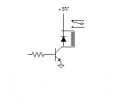
It can be a little tricky picking a photo transistor. They have lots of specs but it is hard to relate them to dawn and dusk sometimes. The LDR in the schematic is tiny 0.2 inches.
If it were me I would buy all the parts from Mouser (just my favorite) then you only pay shipping once and get good parts.
Here is the data sheet.
http://www.mouser.com/ds/2/321/VT900S-203211.pdf
We will try and help you pick a photo transistor if you would rather.

Edit:

Sorry #12. We are just playing ping pong.
 

Thread Starter

RemoWest

Joined Feb 9, 2015
33
That would be great, I would really appreciate that. That was one of my issues from the onset of this project. I didn't really know what to pick for components, or if I even had the right parts at all.
 

Thread Starter

RemoWest

Joined Feb 9, 2015
33
Ok, ya, maybe he can help too?

He kinda dropped-off when you posted the pro schematic..haha:D

Ya, I really would like to use a dark/shaded style phototransistor on this project. I actually have the project functioning at present. I just need to incorporate the night sensor to finish it. I'll try to get a picture within a couple days to post-up. it'll give you guys an idea of what I'm working on.. I always like to know what I'm actually helping people with.

I do appreciate the help from you guys. It was really cool to get help right away. A lot of times people won't even reply on forums. This was a very good initial experience.
 
Last edited:

#12

Joined Nov 30, 2010
18,224
This is the design I made. Much more picky about what it calls, "night".

http://forum.allaboutcircuits.com/blog/night-detector.658/

I just don't understand the problem with the, "I want a phototransistor". They all pass nano-amps when dark and milliamps when lighted. That's about 20,000 to 1 difference. What's the problem? Pick one and expect a milliamp or more for, "light". That would mean changing the 56k in Rons circuit to 7.5k if the amount of light that produces 1 milliamp is the amount of light you want. How about a 750 ohm resistor and a 10k pot?
 
Last edited:

Thread Starter

RemoWest

Joined Feb 9, 2015
33
There's not really a problem per se. it's a visual or aesthetic concern. The project needs to "look" good, and I may be obsessing a bit. :rolleyes::D

If it helps, I "need" a sensor, that at least it seems to me, that IS just that. A sensor that is, or can be adjusted particularly to "night" VS day. I need mine to stay OFF until about what I'd call "light-dusk" that may be quite subjective, but you probably get the idea.

In general I don't know if it helps, or huts more, that I know enough to be "dangerous" with respect to electronics. But when it comes to design I basically know very little. So I'll totally rely on you guys.

I appreciate the patience, and information.
 
Last edited:

Thread Starter

RemoWest

Joined Feb 9, 2015
33
This is the design I made. Much more picky about what it calls, "night".

http://forum.allaboutcircuits.com/blog/night-detector.658/

I just don't understand the problem with the, "I want a phototransistor". They all pass nano-amps when dark and milliamps when lighted. That's about 20,000 to 1 difference. What's the problem? Pick one and expect a milliamp or more for, "light". That would mean changing the 56k in Rons circuit to 7.5k if the amount of light that produces 1 milliamp is the amount of light you want. How about a 750 ohm resistor and a 10k pot?
That's a good unit for another Idea I've had for a while. I would just need it to run for a few hours, at night, instead in 30 minutes.
 

#12

Joined Nov 30, 2010
18,224
There's not really a problem per se. it's a visual or aesthetic concern. The project needs to "look" good, and I may be obsessing a bit. :rolleyes::D

If it helps, I "need" a sensor, that at least it seems to me, that IS just that. A sensor that is, or can be adjusted particularly to "night" VS day. I need mine to stay OFF until about what I'd call "light-dusk" that may be quite subjective, but you probably get the idea.
We gave you all of that...ALL of that. You can stop requesting what we already gave you.
 

Thread Starter

RemoWest

Joined Feb 9, 2015
33
..........
Cool. That shows me how to clock or set the timer on your circuit you drew back in the 80's. I'll have to save that for my lighthouse idea. Thanks man.

I do have questions about the 12V switching circuit that you guys initially helped/ drew for me .
I'm having trouble finding the right components. Assuming I stay with Rons schematic, for simplicity. Do you know what LM 339 I would use? I see a few at mouser, and I have NO idea what one I need. I also need to know what NTD 4906 I need, a few choices there too, but which one? I know resistors are basic enough. But do I need a particular wattage , are the 1/4 watt resistors sufficient? I guess It's better to get the components at mouser, so I'll do that. If you could make recommendations from that site it would be very helpful.

I just don't want to just "assume", and make silly mistakes buying the wrong components. I'm not a guy that designs electrical circuits.... obviously ,right?:(
 
Last edited:

#12

Joined Nov 30, 2010
18,224
You don't want an LM339, in my opinion. It's a quad. Nearly any op-amp or comparator will work in that position, even an LM741, except an op-amp won't need the 2.2k resistor. The resistors will be good at 1/4 watt except R7. If you make that 750 ohms, it should be 1/2 watt. I suppose D1 will be replaced with a 12 volt DC relay. Here's a drawing of where to put a protection diode.

I'm not up on the latest amplifier chips. Maybe Ron can suggest a single for you.

Mostly, you download the datasheet for any particular part to find the suffix for the package you want to deal with.
 

Attachments

Thread Starter

RemoWest

Joined Feb 9, 2015
33
You don't want an LM339, in my opinion. It's a quad. Nearly any op-amp or comparator will work in that position, even an LM741, except an op-amp won't need the 2.2k resistor. The resistors will be good at 1/4 watt except R7. If you make that 750 ohms, it should be 1/2 watt. I suppose D1 will be replaced with a 12 volt DC relay. Here's a drawing of where to put a protection diode.

I'm not up on the latest amplifier chips. Maybe Ron can suggest a single for you.

Mostly, you download the datasheet for any particular part to find the suffix for the package you want to deal with.
Ok. So, if I use a LM174, I would drop the 2.2K resistor all together? So then, which LM174 would I use, you say.. 'nearly any". Are they all pretty much the same for my application? I don't know enough about these components to tell what I need? I'm only asking because I have no Idea. If not you, maybe Ron can make a suggestion.

In position "M1" , I see a NTD4906, what one would I need there. again, I see several on the Mouser site, and I have no idea how to choose one for my application.

With respect to position "D1" in the schematic. That is my 12 V output, correct? ,If so the circuit will be 12 V of course, but the Amp draw will be pretty low as I'm running micro LED's. Do I really "need" a relay? If so, again, what would you suggest?
 

#12

Joined Nov 30, 2010
18,224
There is no such thing as an LM174. Please check your Dyslexic glasses.
The LM741 is so old and feeble that it is a running joke here, but it will work in this position.
If you use an op-amp, an op-amp won't need the 2.2k resistor. "Not need" means, "don't install it", or, "doesn't exist".

"In position "M1" , I see a NTD4906, what one would I need there. again, I see several on the Mouser site, and I have no idea how to choose one for my application"

Look on the left side of the page. See the pictures? Choose one you will be able to solder on to a circuit board.
http://www.mouser.com/Search/Refine.aspx?Keyword=NTD4906

"With respect to position "D1" in the schematic. That is my 12 V output, correct?"
Not quite. You have to connect 12 volts to your LEDs and then connect them to the transistor.
LEDs need resistors to work. That is a whole 'nuther conversation.
http://forum.allaboutcircuits.com/showthread.php?t=19075
That transistor will work for quite a few LEDs.
 

ian field

Joined Oct 27, 2012
6,536
I have been looking around for a unit/module that switches to 12 V power (at night), when the photo sensor is triggered.
I have seen quite a few units and schematics online and youtube. I have seen varying designs and configurations on sale on ebay and other sites. ..But none really are exactly what I'm after.

I have some good basic electronics knowledge, but in no electrical engineer by far. And as easy as this circuit would seem to some, Im lost. My research has left me a bit overwhelmed and confused. Many of the videos and schematics leave alot to be desired. Some use components that others do not. Some list or use components that are unattainable or vague, leading to further confusion. I wouldn't think it would be this hard to do. I feel I've gone as far as I can on my own... I need help. :confused: :(

What I need is a specific circuit that operates on 12 V, that switches to power at night. And uses a photo sensor that I can adjust the sensitivity on. I need the unit to be as small as possible. Ultimately, I'm powering 12 V lights.

I figured I should ask here first, as maybe something already exists that can be modified VS designing a new circuit. The only concern I have with using a preexisting unit is possibly the size. I really need this to be as small as possible for my particular application.

If nothing exists that can be modified, hopefully I can get some of you to show me a design/schematic that would do the trick... And that I could currently get all the parts for.

I appreciate any and all input on this project. :)
Look on this site:

http://ee.old.no/library/

Most of the electronics construction kits include at least one light/dark detector, they all use the Cd-S LDR which is not RoHS compliant - but eBay still has plenty from China.

Some time ago; contractors did the emergency lighting and alarms in the flats where I live - I managed to rescue one of the twilight sensing outdoor lights they ripped out, the circuit I traced used a regular photodiode which is better suited to IR wavelengths - but it evidently worked. Maybe I can find the scan of that schematic if you need it.
 

Thread Starter

RemoWest

Joined Feb 9, 2015
33
There is no such thing as an LM174. Please check your Dyslexic glasses.
The LM741 is so old and feeble that it is a running joke here, but it will work in this position.
If you use an op-amp, an op-amp won't need the 2.2k resistor. "Not need" means, "don't install it", or, "doesn't exist".

"In position "M1" , I see a NTD4906, what one would I need there. again, I see several on the Mouser site, and I have no idea how to choose one for my application"

Look on the left side of the page. See the pictures? Choose one you will be able to solder on to a circuit board.
http://www.mouser.com/Search/Refine.aspx?Keyword=NTD4906

"With respect to position "D1" in the schematic. That is my 12 V output, correct?"
Not quite. You have to connect 12 volts to your LEDs and then connect them to the transistor.
LEDs need resistors to work. That is a whole 'nuther conversation.
http://forum.allaboutcircuits.com/showthread.php?t=19075
That transistor will work for quite a few LEDs.

Dyslexia happens! :eek::p:( sometimes it's fun, sometimes it's not so fun...

Thanks for clarifying the NTD4906 question.

My LED's are on a continuous strip with resistors. They are powered by 12 Volts.
 
Top