10KHz Clock divided by 1000

Thread Starter

dori123

Joined Mar 14, 2019
18
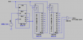
I want to implement 10kHz square wave generator with pulse width 100ns. If I chain the three ICs as shown in (a) or two ICs in (b), the both divide 10MHz clock by 1000, can I get the pulse wave in 0.1% duty cycle?

Thank you in advance.
 

Attachments

WBahn

Joined Mar 31, 2012
32,823
If you want a duty cycle of 0.1%, then you need something that changes with the period of the original 10 MHz signal. But if you've divided the frequency of the signal (multiple times), how would there be anything that survives with that short a period?
 

AnalogKid

Joined Aug 1, 2013
12,126
I want to implement 10kHz square wave generator with pulse width 100ns.
Depends on the accuracy you need. If the 100 ns can be +/- a few percent, then you can drive an R-C network with the 10 kHz signal, with a gate as an output buffer. If you want the 100 ns to derived directly from the 10 MHz signal, then you can follow post #3, with three counters and a 2-in AND gate.

Didn't this question pop up somewhere about a month ago? Sure sounds familiar.

ak
 
Last edited:

danadak

Joined Mar 10, 2018
4,057
One approach, needs one line of code typed,

Code:
PWM_1_Start( );
upload_2019-6-15_5-48-15.png


Could also do this with ATTINY85, Arduino, just about any processor.


Regards, Dana.
 

Thread Starter

dori123

Joined Mar 14, 2019
18
I posted a similar question a couple of months ago, seeking a solution.

Since I am not familiar with Arduino, nor am I good at programming, I think the BCD counter is a better approach.

Since maximum clock frequency of CD4017 is limited to 5.5MHz, 74HCT390 is used to divide the 10MHz clock by 10. So could you elaborate on this approach?

Regards,

dj
 

eetech00

Joined Jun 8, 2013
4,705
Hello

How about a 74HC4040 12-bit counter?
You could use it count down 10Mhz to 10Khz (close anyway). You'd still have to change duty cycle though..

eT
 

Thread Starter

dori123

Joined Mar 14, 2019
18
In the attached circuit, is the pin connections to the AND gate correct? If so, am I supposed to get the pulse width of 100ns in 0.1% duty cycle?

Regards,

dj
 

Attachments

Last edited:

Analog Ground

Joined Apr 24, 2019
460
If the 100 nsec output pulse is to be accurate, any sort of ripple counting in the output should be avoided. The output should be totally synchronous. The diagram shows what I mean. The 10 MHz clock goes to the divide by 1000 counter (any flavor) which is followed by an output flip-flop. One state of the counter (usually all 0s) is decoded and causes the output FF to go active for one clock cycle. For really tight timing, the low-to-high and high-to-low delay times of the FF must be equal. This is not easy if you need sub-nanosecond accuracy. BTW, the output pulse is an output of the FF.

Div1000CounterDiagram.jpg

Also: https://www.allaboutcircuits.com/textbook/digital/chpt-11/synchronous-counters/
 
Last edited:

djsfantasi

Joined Apr 11, 2010
9,237
If the 100 nsec output pulse is to be accurate, any sort of ripple counting in the output should be avoided. The output should be totally synchronous. The diagram shows what I mean. The 10 MHz clock goes to the divide by 1000 counter (any flavor) which is followed by an output flip-flop. One state of the counter (usually all 0s) is decoded and causes the output FF to go active for one clock cycle. For really tight timing, the low-to-high and high-to-low delay times of the FF must be equal. This is not easy if you need sub-nanosecond accuracy. BTW, the output pulse is an output of the FF.

View attachment 179786

Also: https://www.allaboutcircuits.com/textbook/digital/chpt-11/synchronous-counters/
But if the last stage of your divide circuit is a flip flop, how are you going to maintain a 0.1% duty cycle? The flip flop will change the divided clock to a 50% duty cycle.
 

Analog Ground

Joined Apr 24, 2019
460
But if the last stage of your divide circuit is a flip flop, how are you going to maintain a 0.1% duty cycle? The flip flop will change the divided clock to a 50% duty cycle.
The last flip flop "shadows" or follows the decoded output of the counter. If the decoded output of the counter is active for one clock cycle, the flip flop will be active for one clock cycle. It is a "D" flip flop. If it was a toggle flip flop or "T" type, then, yes, it would then be a 5kHz square wave. It is only there to retain the timing of the 10 MHz clock as closely as possible and produce an accurate 100 nsec pulse. This is the whole point of using a fully synchronous design for the output pulse. If the decode was done in such a way to produce accurate enough timing, then the output flop is not needed. The flop gives good timing accuracy in a simple way and the decode does not have to be accurate.

Div1000Timing.jpg

Now, how close will the output be to the clock period? Notice the leading edge of the output pulse is going low-to-high and the trailing edge is going high-to-low. A FF will have different propagation delays from the clock to each edge. For a 74F74 type part (which is very fast) the difference is about 1 nsec (typical). This difference is important to people using these fast parts. So, the data sheet very carefully gives min, typical and max for each edge. So, around 1% accuracy in relation to the 100 nsec clock is expected. The popular HC and HCT parts are very slow and will not be even close to 1%. The data sheets may not even give different specs for the two edges. As I said in my original post, getting sub-nanosecond accuracy takes exotic stuff.
 
Last edited:

crutschow

Joined Mar 14, 2008
38,503
In the attached circuit, is the pin connections to the AND gate correct? If so, am I supposed to get the pulse width 100ns in 0.1% duty cycle?
No, a simple AND gate won't work for what you want.
You will get a 10MHz square-wave output as long as the /Q5-9 output is high.
A circuit with memory is needed.

Below is an example circuit using one 74HC74 D-FF package, that will give a single 100ns pulse each time the /Q5-9 output goes high.
It enables FF U3 for one 10MHz clock pulse.
(The 10:1 10MHz clock divider circuit is not shown).
Note that the CD4017 Reset input needs to be low for it to count.

upload_2019-6-15_12-22-36.png
 
Last edited:

djsfantasi

Joined Apr 11, 2010
9,237
The last flip flop "shadows" or follows the decoded output of the counter. If the decoded output of the counter is active for one clock cycle, the flip flop will be active for one clock cycle. It is a "D" flip flop. If it was a toggle flip flop or "T" type, then, yes, it would then be a 5kHz square wave. It is only there to retain the timing of the 10 MHz clock as closely as possible and produce an accurate 100 nsec pulse. This is the whole point of using a fully synchronous design for the output pulse. If the decode was done in such a way to produce accurate enough timing, then the output flop is not needed. The flop gives good timing accuracy in a simple way and the decode does not have to be accurate.

View attachment 179792
How about some timing on your clock? The output pulse length looks like twice the clock width. The output pulse width (duty cycle) has to be the same as the clock. Your diagram looks nice, but the clock only has a 0.1% duty cycle. Your example looks more like a 50% duty cycle.
 

Analog Ground

Joined Apr 24, 2019
460
If you want a duty cycle of 0.1%, then you need something that changes with the period of the original 10 MHz signal. But if you've divided the frequency of the signal (multiple times), how would there be anything that survives with that short a period?
Good question. I posted how to do this with a synchronous design and a flip flop at the output.
 

djsfantasi

Joined Apr 11, 2010
9,237
The last flip flop "shadows" or follows the decoded output of the counter. If the decoded output of the counter is active for one clock cycle, the flip flop will be active for one clock cycle. It is a "D" flip flop. If it was a toggle flip flop or "T" type, then, yes, it would then be a 5kHz square wave. It is only there to retain the timing of the 10 MHz clock as closely as possible and produce an accurate 100 nsec pulse. This is the whole point of using a fully synchronous design for the output pulse. If the decode was done in such a way to produce accurate enough timing, then the output flop is not needed. The flop gives good timing accuracy in a simple way and the decode does not have to be accurate.

View attachment 179792

Now, how close will the output be to the clock period? Notice the leading edge of the output pulse is going low-to-high and the trailing edge is going high-to-low. A FF will have different propagation delays from the clock to each edge. For a 74F74 type part (which is very fast) the difference is about 1 nsec (typical). This difference is important to people using these fast parts. So, the data sheet very carefully gives min, typical and max for each edge. So, around 1% accuracy in relation to the 100 nsec clock is expected. The popular HC and HCT parts are very slow and will not be even close to 1%. The data sheets may not even give different specs for the two edges. As I said in my original post, getting sub-nanosecond accuracy takes exotic stuff.

Let’s do some math. The circuit requirements are as follows.
  • 1 nanosecond on
  • 99 nanoseconds off
After the divide by 1000, the output should be on for 1 nanosecond and off for 999,999 nanoseconds or 999.99 microseconds.

That’s why I questioned your solution.
 

Analog Ground

Joined Apr 24, 2019
460
How about some timing on your clock? The output pulse length looks like twice the clock width. The output pulse width (duty cycle) has to be the same as the clock. Your diagram looks nice, but the clock only has a 0.1% duty cycle. Your example looks more like a 50% duty cycle.
I think the original poster wants a pulse out which has a width the same as the period of the clock. 100 nsec pulse at a rate of 10 KHz. If this is the case, then I think my timing is correct. But, I am often wrong in interpreting a posters requirements.
 

djsfantasi

Joined Apr 11, 2010
9,237
..,divide 10MHz clock by 1000, can I get the pulse wave in 0.1% duty cycle?
As I slso misinterpret TS requirements. Your interpretation appears to be right after re-reading the thread. Sorry for arguing with you, but - hey - sometimes that’s for the better
 

WBahn

Joined Mar 31, 2012
32,823
Good question. I posted how to do this with a synchronous design and a flip flop at the output.
Yep. There are a number of ways to do it, but all are going to require bringing forth something at the original clock rate.

The "simplest" would be to use a 10-bit (or more) counter with that decodes the 999 state and resets the counter on the next rising clock edge. The flip flop input then needs to be fed with a signal that decodes one of the states (probably state 0).

I definitely agree that the design should be fully synchronous -- any asynchronous element in something like this is begging for glitches.

There are other ways to do it that would involve dividing down the clock, you just need to be sure that you can decode one and only one overall state that is one period of the master clock. Depending on the capabilities of the chips used to do the division, this might be very easy to not. This approach should result in less power consumption than simply running a counter at 10 MHz.
 
Top