1000uf Capacitor slow starting circuit

Thread Starter

Tony Elliott

Joined May 8, 2015
158
Hi All,
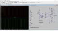
I am using 1000 uf capacitor in this 10v to +\- 5v converter. This retains the square wave shape going into this circuit at low frequencies. but when plugging into the circuit it takes about 10 seconds to work due to the large 1000uf cap and I can see on the scope the squrewave slowly appearing going from 0 to 10v slowly down to +/- 5. Is there any way to remedy this? I had an idea maybe use lots of smaller caps that add up to 1000uf?

FullSizeRender.jpg
 

bushrat

Joined Nov 29, 2014
209
Smaller caps totaling 1000 uF will give you same results. The time it takes to charge a capacitor depends on your your input resistance to your capacitor (RC constant). R * C = 1 tau. it takes 5 tau's to fully charge a capacitor. What is your R?
If it takes 10 sec to fully charge your cap, then 1 tau is 2 seconds... 2 sec / .001 F = 2 k ohms (input impedance).. am I right?
You can lower the resistance, but that will take more current, and you need to be careful not to overheat your components.

After looking at your schematics, I think the limitation is the opamps that you are using. They are most likely not high-power opamps, and provide low current.
 

DGElder

Joined Apr 3, 2016
351
Hard to believe you need 1 mF capacitors for a good square wave. What happens when you use 100uF caps instead?

Since you have a symmetry adjustment voltage at the + opamp input, instead of tying it to ground, why not direct couple the first stage and adjust the + input to +5V or whatever you need.

These are rhetorical questions - just shotgunning ideas.
 
Last edited:

Alec_t

Joined Sep 17, 2013
14,314
How low are the low frequencies?
Your circuit shows two amplifier stages. How do they produce +/-5v?
What are the amp supply voltages?
 

Thread Starter

Tony Elliott

Joined May 8, 2015
158
The square wave goes down to about 1 Hz. On the converter I use a TL074. As you can see on the schematic the 1M ohm pot attenuates the vertical bias.

QFT. You need <-5v supply to get out -5v.
The amp power supplies are +/- 12v. I could put a stronger squarewave signal in to the converter circuit? At the moment it is 0 to 5 v I could put it up to 10v then add a resistor after the capacitor?
 
Last edited by a moderator:

DGElder

Joined Apr 3, 2016
351
Is the input a constant 0-10V magnitude and duty cycle square wave or can it continually change? If it is constant (constant enough that changing the pot setting is not a hassle) you just set the + input to 5V bias and remove the coupling capacitor to the first stage and you can use a much smaller coupling capacitor to the second stage.
 

Thread Starter

Tony Elliott

Joined May 8, 2015
158
Thank you for the schematics, I'll try these out:)

The frequency is adjusting as I am using a square wave oscillator for modular synth purposes.
 
Last edited by a moderator:

Thread Starter

Tony Elliott

Joined May 8, 2015
158
Why use the square wave to make -5 volts when a -5 volt regulator off the -12 volt supply is so much simpler?
The squarewave oscillator runs off of a 12v battery. Could I attenuate the squarewave signal down to +5v, 0 as ground and the -5 v from the power supply, put two 100uf capacitors between -5 ground and +5???
 
Top