1 out of 20 LM301AN works properly

Thread Starter

PeteHL

Joined Dec 17, 2014
596
In this configuration of LM301 as a fast inverting half-wave rectifier, out of my on-hand stock of 20 ICs, I found only one that gives me a clean and stable trace on my scope. I was looking at the output of the below circuit where the input is a 1 kHz sine wave about 1V peak.

This is stock that is probably at least ten years old. So is the problem that these ICs have deteriorated in some way, or is there some other reason?

Initially I was testing this circuit on a socket board, but having so much difficulty with getting a good output, I switched to building it on strip board. There is an excellent output with only one in the socket on my soldered circuit.

Thanks if anyone knows what is going on here,
Pete
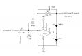
Fast-HW-RECT.png
 

danadak

Joined Mar 10, 2018
4,057
Scope captures, can you post them ?

A LM301 should not degrade unless they have been stored damp over
an extended time, or experienced high rep rate of thermal cycling one
extreme to another. Or not stored anti static, you would see bias current
effects if that were true in the best case, catastrophic in the worst.

Regards, Dana.
 

AlbertHall

Joined Jun 4, 2014
12,660
Thanks if anyone knows what is going on here,
Make sure the supplies to the LM301 are well decoupled close to the IC pins.
Your circuit uses feed-forward compensation and from the datasheet:
"When feed-forward compensation is employed, however, it is advisable to bypass the supply leads of each amplifier with low inductance capacitors because of the higher frequencies involved."
 

Thread Starter

PeteHL

Joined Dec 17, 2014
596
Scope captures, can you post them ?

A LM301 should not degrade unless they have been stored damp over
an extended time, or experienced high rep rate of thermal cycling one
extreme to another. Or not stored anti static, you would see bias current
effects if that were true in the best case, catastrophic in the worst.

Regards, Dana.
Unfortunately I have an old cathode ray oscilloscope, so captures would be at least difficult. Except for the one op-amp, where the time point of the half-waves starting is shifting back and forth. The negative half-waves are not a distinct and bright trace, but rather dull and spread out in curves that are a distorted sine wave.

The ICs have been stored in anti-static tubes and not subjected to high humidity or temp. extremes.

Thanks
 

Thread Starter

PeteHL

Joined Dec 17, 2014
596
Make sure the supplies to the LM301 are well decoupled close to the IC pins.
Your circuit uses feed-forward compensation and from the datasheet:
"When feed-forward compensation is employed, however, it is advisable to bypass the supply leads of each amplifier with low inductance capacitors because of the higher frequencies involved."
Thank you, I have not done power supply bypassing and will try that.

-Pete
 

danadak

Joined Mar 10, 2018
4,057

Thread Starter

PeteHL

Joined Dec 17, 2014
596
Connecting a 10 k Ohm resistor from output (junction of R1 and D1) to ground removed the distortion. In my previous testing, the only load that the circuit saw was the channel input impedance of the scope.

Partial power supply bypass did not fix the problem. That is, I connected 100 nF ceramic disc capacitors from and close to the power pins to ground.

Edit, written later in the day: When I built the circuit again on socket board, I got a good output to my scope without power supply bypassing or connecting a 10 k Ohm resistor from the circuit's output to ground. I have no idea where the distorted waveform was coming from. So anyone don't take what I've said to mean that relatively low resistance loading of the circuit is absolutely required to get it operating properly.
 
Last edited:

Thread Starter

PeteHL

Joined Dec 17, 2014
596
Try connecting C1 between pin1 and pin8?
SG
For my application I need the fastest possible rectification. Feed-forward compensation as shown in the schematic of my first post is the fastest. Connecting a 30 pF capacitor from pin 1 to pin 8 (single pole compensation) is slower than feed-forward.
 

dendad

Joined Feb 20, 2016
4,642
It is good practice to always add bypassing close to the power pins, whether you see improvements or not.
On my PCB designs, each IC has a decoupling cap, and then the power rails have them every now and then too. Caps are cheap and save a lot of headaches. Bad power = bad operation.
 

Thread Starter

PeteHL

Joined Dec 17, 2014
596
id say the parts are simply not cutting it for the application.

One of them works bcz better than spec or has some anomaly
No, I was seeing waveform distortion and an unstable trace with the output of a function generator at input to a single half-wave rectifier, and the output of the rectifier to a channel input of the scope (CRO). Test signal was a 1 kHz sine wave about 1 Vpk.
It is good practice to always add bypassing close to the power pins, whether you see improvements or not.
On my PCB designs, each IC has a decoupling cap, and then the power rails have them every now and then too. Caps are cheap and save a lot of headaches. Bad power = bad operation.
Is your power supply decoupling a 100 nF disc ceramic in parallel with a 10 uF tantalum capacitors?
 

dendad

Joined Feb 20, 2016
4,642
Is your power supply decoupling a 100 nF disc ceramic in parallel with a 10 uF tantalum capacitors?
That should work well.
I use 100nF ceramic chip caps and 10uF tants. And most of my boards are surface mount. Now I can get 10uF 1206 ceramic chip caps and I use some of them too.
 
Top