How does a dipole antenna work?

Thread Starter

spark360z

Joined Jul 27, 2012
10
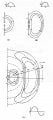
I've just started to learn about an antenna theory.

According to the attached image.

Can anybody explain what's going on in the image?

I've done lots of calculation, but still have no idea what's going on.

My question is

1. How dipole produce a loop of electric field? (How a loop of electric field are made?)

2. Why does the bigger loop of electric field produce high electric field

and lower as the loop become smaller?

3. Why does the smallest loop produce the highest magnetic field?

(Isn't loop of higher electric field produce higher magnetic field?)

Sorry for my bad English.
 

Attachments

Papabravo

Joined Feb 24, 2006
21,159
It works because an alternating current is present in a pair of conductors which produces alternating electric and magnetic fields. Depending on the frequency of the signal, and the length and arrangement of the conductors, a portion of the signal power is radiated into space and a portion is reflected back to the source.
 

Thread Starter

spark360z

Joined Jul 27, 2012
10
Thanks for the reply.

but I still confuse, because from what I know, an electric field line is a line from +Q to -Q

And we're dealing with alternating current, so from I=dQ/dt, and "I" represent how fast Q moving not size of the Q, so Q is the same.

How can E increase since Q is the same?
 

Papabravo

Joined Feb 24, 2006
21,159
The charges move back and forth in the conductors. In one direction dQ/dt is positive and in the other direction it is negative. The voltage along the conductor will vary with time and position and consists of both standing waves and traveling waves.
 
Last edited:

davebee

Joined Oct 22, 2008
540
There is a lot of activity taking place in the resonating antenna.

You're right that an electric field line is a line from +Q to -Q, but in the antenna, the charges are constantly re positioning themselves, so the field lines grow and shrink over time.

Suppose you have an electrically neutral antenna. Now imagine that some + charges have been separated to one end, and some - charges have separated to the other end. Electric field lines will exist between the two ends.

Now imagine that the + charges and the - charges start moving back towards each other due to their electrical attraction. As they meet and neutralize each other, the electric field lines will start to get weaker, but because charges in motion are a current, magnetic field lines will start to grow.

The electric fields weaken as the magnetic fields grow, until the charges meet in the center of the antenna, there are no electric fields, and the magnetic field lines are at their maximum. With no electric field, there is no more force pushing the charges, so the current reaches a peak and starts to decay. As the charges slow down, the corresponding magnetic field decreases in strength.

But from there, the collapsing magnetic fields will continue to drive the current, so as the magnetic field lines weaken, the charges will separate again in the other direction, and electric fields will begin to form again as the collapsing magnetic fields continue to separate the charges.

In this way, the charges travel back and forth in the dipole like the swing of a pendulum, and the corresponding electric and magnetic fields grow and shrink.

Meanwhile, almost as a separate activity, the accelerating charges will radiate electromagnetic radiation. Unlike the previously described electric and magnetic "near" fields, the EM electric and magnetic "far" fields are in phase, and instead of being returned to the system, the energy that goes into the EM fields is radiated away at the speed of light.
 

tinamishra

Joined Dec 1, 2012
39
Nice information is provided here but i would like to share some related information depends on specific condition that is In my case it does not despite having the resonant loading coil situation. I measured the audio response with the upper audio frequency response of the transmitter at the final modulator to be 21 kHz.and that of the transmitted signal previously to be up to 13 kHz. From this it appears that the antenna system BW is 26 kHz. The radiator is half length of 1/2 inch and tapers down to 3/8 inch.
If the limited bandwidth due to antenna Q were a factor this would make the THD appear to be lower. In today's measurement the receiver bandwidth used was 10 kHz which yields an audio BW or 5 kHz so this is dominant over the antenna BW. The combination of the 800 Hz tone and the 10 kHz receiver BW allows for the inclusion of 5 harmonics.
 

Papabravo

Joined Feb 24, 2006
21,159
Nice information is provided here but i would like to share some related information depends on specific condition that is In my case it does not despite having the resonant loading coil situation. I measured the audio response with the upper audio frequency response of the transmitter at the final modulator to be 21 kHz.and that of the transmitted signal previously to be up to 13 kHz. From this it appears that the antenna system BW is 26 kHz. The radiator is half length of 1/2 inch and tapers down to 3/8 inch.
If the limited bandwidth due to antenna Q were a factor this would make the THD appear to be lower. In today's measurement the receiver bandwidth used was 10 kHz which yields an audio BW or 5 kHz so this is dominant over the antenna BW. The combination of the 800 Hz tone and the 10 kHz receiver BW allows for the inclusion of 5 harmonics.
I have absolutely no idea what you are talking about. First of all what is the frequency of the RF carrier we are talking about? Second of all, are we talking about voice modulation? What started this thread was how a dipole antenna works. Practically speaking the bandwith of a dipole antenna gets narrow at VLF (30-300 kHz) and much wider at VHF (30-300 MHz)
 
Top