Facebook
 Google
 GitHub
 Linkedin
So I'm staring at this chip and forgotten all my ECE stuff from college.
http://www.national.com/ds/LM/LM3914.pdf
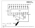
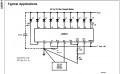
The basics of what I'm trying to do is to hook up a flex sensor to the signal input and have the led graph light up as the sensor is straightened. (sensor is 10k straight and max 30-40k completely bent). The power source will be a 12v car battery. I plan to attach the sensor to a gas pedal in a car and have the graph light up as you press on the pedal.
Anyway, here are my questions:
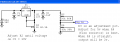
1) I know nothing of capacitors. What kind do I need for this application? It goes on the negative wire to the LEDs to keep the right amount of voltage correct? (LEDs are 3v max iirc).
2) I know RLo is the low voltage (eg 0v-12v with RLo grounded and 3v-12v if RLo has a 3v feed). Why is RHi connected to ROut if it is higher than 5v?
3) What IS Ref Adj?!
4) any suggestions to help my n00b self out? I have a few books but they don't seem to be helping much.
http://www.national.com/ds/LM/LM3914.pdf
The basics of what I'm trying to do is to hook up a flex sensor to the signal input and have the led graph light up as the sensor is straightened. (sensor is 10k straight and max 30-40k completely bent). The power source will be a 12v car battery. I plan to attach the sensor to a gas pedal in a car and have the graph light up as you press on the pedal.
Anyway, here are my questions:
1) I know nothing of capacitors. What kind do I need for this application? It goes on the negative wire to the LEDs to keep the right amount of voltage correct? (LEDs are 3v max iirc).
2) I know RLo is the low voltage (eg 0v-12v with RLo grounded and 3v-12v if RLo has a 3v feed). Why is RHi connected to ROut if it is higher than 5v?
3) What IS Ref Adj?!
4) any suggestions to help my n00b self out? I have a few books but they don't seem to be helping much.