Trio-Kenwood Oscilloscope CS-1060 (different scope to last post) intensity adjustment persistently on full

Status
Not open for further replies.

Thread Starter

Tp86

Joined Sep 13, 2023
210
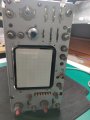
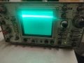
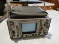
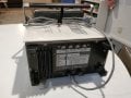
I purchased a oscilloscope in hope that it will be too difficult of a repair and also to gain some more insight into the methodolgy and to gain more knowledge on real world circuits.

The particular fault on this oscilloscope is that the intensity of the oscilloscope beam is constantly so bright it both burns my retina and most likely is causing damage to the phospher coating.

To describe the fault in more detail: as i turn the intensity knob, it does not seemt o alter the intensity at all but it does seem to slightly narrow the focus as I increase the intensity level.
Furthermore, the focus pot seems to be adjusting the focus properly as far as i can tell (just for some more info)
I've included a short video to demonstrate in case it helps to get a picture of what I mean (its its hard to film bright light though)

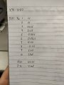
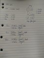
I have researched the inner workings of the crt and have an idea of what the biasing pins at the input of the crt. The pin inparticular I would suspect would be faulty would the the control grid, G1. Whereby a negativly charged grid repell the electrons out the electron guns heater element. The more negative potential here the less that will make it through the grid and thus the less electrons to make it to the phosphor. So I would assume this voltage is: 1. not variable 2. constantly on a higher voltagage than say -15VDC

What I've done:
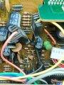
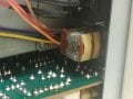
- I've located the intensity pot (which contains 2 VR's in one package as you can pull it out to add just second VR) and sprayed it the best I could with WD-40 Specialist Electrical Contact Cleaner and tried to work it back and forth. The second VR (when you pull knob) is for astigmatism adjustment and as far as I can tell its working as it focuses the beam wider and narrower
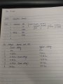
- Looked at the schematic for some hints:
- I noticed there is an 'Intensity Adjustment' section under the adjustments heading which says you can adjust a certain pot (VR5) to perform an adjustment however I tend to think its not this as I cant adjust it at all currently
- In the troubleshooting section I notice there is a section for 'Intensity' with a yes or no condition (it doesn't explicitly say what intensity means in this context) and it suspects the following transistors and diodes. It could be a clue?
1744282391156.png
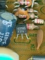
- Following the path of the intensity pot back to Trig Unit (X74-1470-01) I notice it controls the base of Q25. Would this be a good transistor to check first? (Mind you this board is hard for me to access as I have to try remote main of the front controls including time base adjuster. Let me know what you think!) After that transister I can see the -15V will base through many other transisters and IC's but I've not gone that far yet as Im not sure if Im on the correct track
1744282300617.png

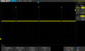
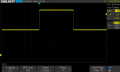
Short video showing the fault but was hard to show on camera due to light
 

Attachments

Irving

Joined Jan 30, 2016
4,996
Do the following checks:
1: Are +15 and -15v rails correct?
2: does the voltage at the centre tap of the VR vary from -0.6v to -15v as expected?
3: Does that same variation appear at the base of Q25?
4: What's happening at the collector of Q25?
5: What's happening at the emitter of Q25?
 

Thread Starter

Tp86

Joined Sep 13, 2023
210
Do the following checks:
1: Are +15 and -15v rails correct?
2: does the voltage at the centre tap of the VR vary from -0.6v to -15v as expected?
3: Does that same variation appear at the base of Q25?
4: What's happening at the collector of Q25?
5: What's happening at the emitter of Q25?
1. Results tested from P24 headers (unplugged)
- the 15v pin and -15v pin, 5v pin and 120V pin seems to be okay
- the 50V pin (pin 4) is reading 65.6V
- the TP10 is reading 120V but TP12 is reading -2.1mV. The manual states it should be 120V under the 'Reference voltage (+120V) adjustment' section below. These measurements were taken with P24 plugged back into header

1744350353132.png

1744350210294.png

It seems like something is not right here but I dont know if it's related to the intensity fault. What do you think? Is it possible there is a typo in the manual and they meant to type TP10 instead of TP12? I added a picture of this test point and it seems to be completely isolate so they must mean TP10 for calibrating the 120v
On this page in manual it says TP10 is a 'high voltage check' and TP12 it says nothing about high voltage
1744350902652.png
 

Attachments

Last edited:

Thread Starter

Tp86

Joined Sep 13, 2023
210
Sorry, I hadn't noticed that there was more than one S2. The one I'm referring to is S2 in the Trig diagram, S2 Coupling.
Its ok. I've noticed TP12 is on both boards. I tested continuity of both TP12 to ground both are direct short so its definently ground plane. I'm guessing it's a typo in manual it should be a voltage measurement form TP10 to chassis for measuing the 120VDC

1. Results tested from P24 headers (unplugged)
- the 15v pin and -15v pin, 5v pin and 120V pin seems to be okay
- the 50V pin (pin 4) is reading 65.6V
Ok. So today I tested pin 4 with the P24 plug plugged in and the voltage has dropped to 50.01VDC. So all DC rails are perfect. I'll proceed with other steps Irving
 

Thread Starter

Tp86

Joined Sep 13, 2023
210
2: does the voltage at the centre tap of the VR vary from -0.6v to -15v as expected?
I've taken some measurements of the intensity VR at P25 on X77-1300 (Connection Unit)
The resistance measurements with respect to pin 1 (ground):
- When I tested the resistance between ground and wiper it stayed at 9.8k ohm in the lowest setting and highest setting
- When I tested the resistance between -15V (pin 2) and wiper it varied smoothly from 0.5ohm (lowest) to 9.87k ohm (highest)

I would have thought the wiper to ground would also provide an inverted resistance reading of the pin 2 to wiper?

The voltage measurements I took were with respect to ground (chassis):
- Pin 2 seems like it should always be a steady -15V independent of the location of the pot but when on lowest setting it reads -14.36V and when fully on it reads -0.6mV (it also transitions smoothly to every value in between)
- Yet pin 3, the wiper, reads a constant -14.36V on both lowest and highest setting

Can you make any sense of this? I've never had any experience measuring pots before so its a bit new to me
 

Attachments

Last edited:

bertus

Joined Apr 5, 2008
22,882
Hello,


Is it possible to measure the resistance between the ends of the potmeter?
It could be there is an open end.
Or there is a break in one of the potmeter connections.

Bertus
 

sarahMCML

Joined May 11, 2019
695
I've taken some measurements of the intensity VR at P25 on X77-1300 (Connection Unit)
The results do not make much sense to me:
- When I tested the resistance between ground and wiper it stayed at 9.8k ohm in the lowest setting and highest setting
- When I tested the resistance between -15V (pin 2) and wiper it varied smoothly from 0.5ohm (lowest) to 9.87k ohm (highest)

I would have thought the wiper to ground would also provide an inverted resistance reading of the pin 2 to wiper?

The voltage measurements I took were with respect to ground:
- Pin 2 seems like it should always be a steady -15V independent of the location of the pot but when on lowest setting it reads -14.36V and when fully on it reads -0.6mV (it also transitions smoothly to every value in between)
- Yet pin 3, the wiper, reads a constant -14.36V on both lowest and highest setting

Can you make any sense of this? I've never had any experience measuring pots before so its a bit new to me
You could have a break or bad joint in the circuit to P25 pin 1, or the diode D4 has gone open. Check if you have about -0.6V on pin 1 with respect to chassis. The pot may have an internal break as well.

Edit: Just noticed that bertus has beaten me to it!
 

Thread Starter

Tp86

Joined Sep 13, 2023
210
Hello,


Is it possible to measure the resistance between the ends of the potmeter?
It could be there is an open end.
Or there is a break in one of the potmeter connections.

Bertus
Hi Bertus, when I measured the resistance from pin 1 to pin 2 (which should be either end of the pot) it reads 9.8k ohm. So it would assume there is no break in the pot itself. I do not know how to get the pot out at the this so it might be tricky to test outside of unit. It would be a bit eaiser to remove the PCB that p25 plug plugs into though so I could isolate it. I might have to do that. However on the schematic is says VR3 is a 10K (linear taper) so it seems ok.
1744457349666.png


You could have a break or bad joint in the circuit to P25 pin 1, or the diode D4 has gone open. Check if you have about -0.6V on pin 1 with respect to chassis. The pot may have an internal break as well.

Edit: Just noticed that bertus has beaten me to it!
I did a ohm test from pin 1 to pin 2 as i mentioned to Bertus above in this post and got a reading of 9.8k ohm which is what the schematic says the pot should read so it sort of seems like there may be no break? I think D4 shouldnt matter though because Im testing the multimeter on the pin 1 to pin 3 so it should by pass the diode as the path is in front of it. Yet I understand why variation in resistance from this path (it says stead on 9.8k no matter the intensity pot position)
 

bertus

Joined Apr 5, 2008
22,882
Hello,

Check the connection from pin3 to the wiper of the potmeter.
It could be the voltage on pin3 is coming from somewhere else.

Bertus
 

Irving

Joined Jan 30, 2016
4,996
That's why I suggested doing voltage rather than resistance - resistance measurements are only valid if the VR is out of circuit - ie J25 disconnected and measured on the plug J25 or directly on the VR.

So unplug J25 and repeat resistance measurements on plug or VR. Pin 1 - 2 or outer 2 pins on VR should be 10k. pin 3 to 1, or middle to one end, should vary 0 - 10k and 3 to 2, or middle to other end, should do the reverse ie 10k - 0.

Also while unplugged, on P25 on PCB check pin 2 is -15v. Using diode test mode on multi-meter check pin 1 wrt chassis is open-circuit with probes one way round, and 0.6v approx the other way.
 
Last edited:

Thread Starter

Tp86

Joined Sep 13, 2023
210
That's why I suggested doing voltage rather than resistance - resistance measurements are only valid if the VR is out of circuit - ie J25 disconnected and measured on the plug J25 or directly on the VR.

So unplug J25 and repeat resistance measurements on plug or VR. Pin 1 - 2 or outer 2 pins on VR should be 10k. pin 3 to 1, or middle to one end, should vary 0 - 10k and 3 to 2, or middle to other end, should do the reverse ie 10k - 0.

Also while unplugged, on P25 on PCB check pin 2 is -15v. Using diode test mode on multi-meter check pin 1 wrt chassis is open-circuit with probes one way round, and 0.6v approx the other way.
I think I have figured out the problem and why I am getting confusing results. I believe there is an error in the schematic and pin 2 of P25 is actually the wiper/centre cap instead of the pin 3 it prints in the schematic.

If i measure resistance pin 1 to 2 I get a fluid movement 9.8k to 0.5
If I measure resistance pin 2 to 3 I get a fluid movement 0.5 to 9.8k
If I measure resistance pin 1 to 3 I get a constant 9.8k

Based on this hypothesis pin 2 is outputting correct voltage relative to ground -14.36V (lowest) to -0.6mV (highest)

Do you want me to unplug the P25 to reconfirm results? Its a bit of a pain to get to but not too bad

Edit: I guess next logical step would be to check if P25 Pin 2 and P12 Pin 4 consistently have the same voltage as I vary intensity adjustment
Edit 2: I've confirmed there is a error in the schematic. P25 Pin 2 and P12 Pin 4 have the same voltage as I adjust intensity and P25 Pin 3 always stays constant on -14.36V.

It seems safe to move on to step 3?
 
Last edited:

Thread Starter

Tp86

Joined Sep 13, 2023
210
3: Does that same variation appear at the base of Q25?
4: What's happening at the collector of Q25?
5: What's happening at the emitter of Q25?
3. Yes, same fluid voltage variation (while turning adjustment) appears on base of Q25
The base voltage relative to ground reads -14.38V (on lowest setting) and -0.9mV (on highest) and fluid in between
4. The collector voltage relative to ground reads 7.37V (on lowest setting) and 7.34V (on highest) and fluid in between
5. The emitter voltage relative to ground reads -14.86V (on lowest setting) and -0.62V (on highest) and fluid in between

I've been trying to make sense of these results. I think the emitter voltage varies as it does as when it increases more and more potential is dissipated though R98?
I do not know why voltage at the collector is not changing though. Perhaps it suggests a problem further down the path?

For later: It looks like the voltage to G1 goes through P19's Pin 2 on the same board (Trig Unit)
The more I look at the circuit there is 'INTEN MAX' labled all over the place with what seems to be test points with an
expected dc value for when its at its lowest and highest setting. eg. 1744538827488.png
I suppose these are clues for the repairman to check these dc values are correct?
 

Attachments

Last edited:

Irving

Joined Jan 30, 2016
4,996
The emitter voltage should track the base voltage - 0.6v approx, so that suggests the base-emitter junction of q25 is good.

The level at q25 collector seemingly being fixed at 7.7x volts is possibly indicative of a problem. Simulating that circuit in LTSpice suggests it should vary between 6 and 7.5v over the range of the pot.

If you look at the circuit, you'll see Q25 collector is connected to three resistor networks, each controlled by a transistor to +5v ( Q22-Q24). I believe these are part of the flyback blanking, where intensity is reduced to zero as the spot returns to the start of the scan, or switches from one trace to the other. When all three are off the voltage there determines the intensity.

Using your other 'new' 'scope you could investigate these test points to see if the signals are correct. They should be a pulse that goes to a lower level during the scan, which should match the horizontal sweep time, and the higher level during flyback.
 

Thread Starter

Tp86

Joined Sep 13, 2023
210
If you look at the circuit, you'll see Q25 collector is connected to three resistor networks, each controlled by a transistor to +5v ( Q22-Q24). I believe these are part of the flyback blanking, where intensity is reduced to zero as the spot returns to the start of the scan, or switches from one trace to the other. When all three are off the voltage there determines the intensity.
That is interesting. Well done figuring that out. I guess it is getting this information from the sweep unit or circuitry. During the blanking phase I would think G1 would become more negative or the cathode would become more positive.

After conducting a test on TP6 with everything plugged in (a challenge to access this point) I can confirm there is a repetitive pulse.
DC offset 3.4V
Peak voltage 6V

Period of wavelength 880us (1.136khz) (scope says 1.66khz so my period measurment must be a little off)
Period of pulse 22.5us (Higher potential time)

Because the front of the scope is dissasembled I do not know at this point what time base I am on but I will try to find out. I not sure if the raised potential pulse is the retrace or the lower part at this point
 

Attachments

Irving

Joined Jan 30, 2016
4,996
So does that DC offset change with the intensity control? My interpretation of that is 3.4v is max intensity and 6v is blanked/zero intensity.
 

Thread Starter

Tp86

Joined Sep 13, 2023
210
So does that DC offset change with the intensity control? My interpretation of that is 3.4v is max intensity and 6v is blanked/zero intensity.
Ah yes it does! Well done. Offset is 6V when intensity is lowest, and 3.4V when is it's at it's highest setting. So it seems up to that node everything seems okay?
 
Status
Not open for further replies.
Top