Hi,
I am a student and I am trying to build a heart rate monitoring system.
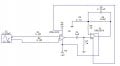
I am having problems with an INA118 instrumentation amplifier, I work on it for a few hours and then when i come back to the next day the amplifier does not work anymore, it keeps going to the rails.
It requires negative and positve supplies and since it can take up +-18V, i am feeding it with 2 9V batteries connected together so that i get +9 and -9V. Does it require a regulated voltage?
When I give my amplifier to my friends who is working on a different project but using the same amplifier, his system does not work, so the amplifier has definetily died out. I am not sure what I am doing that could be killing it, because my circuit is a simple circuit to test it, i feed sine wave signal of 20mvp-peak at 10hz, and set the gain to 20.
I am not sure what the problem is, I am going to use a 5V regulator to supply it with regulated voltage.
Help would be greatly appreciated, Thanks
I am a student and I am trying to build a heart rate monitoring system.
I am having problems with an INA118 instrumentation amplifier, I work on it for a few hours and then when i come back to the next day the amplifier does not work anymore, it keeps going to the rails.
It requires negative and positve supplies and since it can take up +-18V, i am feeding it with 2 9V batteries connected together so that i get +9 and -9V. Does it require a regulated voltage?
When I give my amplifier to my friends who is working on a different project but using the same amplifier, his system does not work, so the amplifier has definetily died out. I am not sure what I am doing that could be killing it, because my circuit is a simple circuit to test it, i feed sine wave signal of 20mvp-peak at 10hz, and set the gain to 20.
I am not sure what the problem is, I am going to use a 5V regulator to supply it with regulated voltage.
Help would be greatly appreciated, Thanks