BC212 Transistor Question (Marshall amplifier repair)

Thread Starter

sweatyk

Joined Aug 13, 2013
55
What I am replacing is a result of a costly mistake. What I did caused TR8 & TR10 to short so I had to replace them. However the short remained after their replacement which meant other damage was still lurking in there. I narrowed it down to TR9 but while I have this opened up I decided to just go thru and replace the trans, diodes, and resistors in that area to freshin it up. This amp gets quite loud and the overdrive channel does have a sweet spot even if most of it is solid state. I realize what you are saying about them not being required for the circuit to work but I just want to put it back like it was being it does not belong to me.

And it is an 8 ohm speaker if that was what you were referring to.
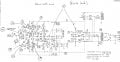
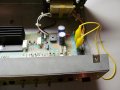
 

studiot

Joined Nov 9, 2007
4,998
What else have you tested?

You usually burn out at least one emitter resistor when you burn out the output pair.

I did not mean that you should permanently omit the protection pair, just that you could fix everything else and get it running nice and sweetly before reinstating them. In fact some measurements may well have been taken without them as they do affect performance slightly.

You still haven't answered my question in bold in my last thread about these transistors.

Have you the facility to check the amp in stages best with a scope but even with a signal tracer?
 

Thread Starter

sweatyk

Joined Aug 13, 2013
55
The way I tested with my limited knowledge was to start where my DMM probe shorted pin 7 & 6 on IC10 (don't ask)....so using the schematic I proceeded to remove transistors and chips from that point on looking for the short. I also lifted out of the circuit to one side various diodes and resistors in the chain. When I finally got to TR9 the short was gone. Remember I'm a novice with common sense but no true understanding of how all of this works. I need to go to school or read all of the training info here on this forum.

The other answer to the question is I do not have access to an Oscope or signal trace and haven't even touched one in over 30 years. Never truely grasped how to be effective using it.

Throughout this process I have a alligator jumper in place of the fuse and the amp is plugged into a current limiter light bulb rig I built but did not want to leave the amp on for fear of starting a fire with that jumper.......lol

One day I hope not to sound like a moron with this stuff because I really like doing it just never had any good training or schooling on it. I've managed to poke around and repair several amps, receivers, and various other electronics but could have probably repaired it a whole lot faster if I had the proper knowledge.
 

Thread Starter

sweatyk

Joined Aug 13, 2013
55
Yes on TR8 and TR10. But I had to substitute them with TIP142 and TIP147 instead of the BDV65c and BDV64c which are hard to find. But they are also BCE. The TR9 will be coming in an order from Mouser sometime this week with the other parts.

Thank you......
 

studiot

Joined Nov 9, 2007
4,998
I have attached a circuit diagram annoted with 18 test points.

Please measure the DC voltage at each of these and post a table or list.

You should attach the black lead of your DVM to the centre zero railand make the measurements with the red lead. This means that some will be negative.
Take great care not to short anything.
 

Attachments

Last edited:

Thread Starter

sweatyk

Joined Aug 13, 2013
55
And I have been plugging it in to a light bulb current limiter so to speak that I constructed to see if there are shorts when I turn it on. Will I need to remove that in order to get a more true voltage reading?
 

studiot

Joined Nov 9, 2007
4,998
The power supply is known as split rail, which means that there are two supplies one plus, one minus about zero. This zero starts at the centre tap of the power transformer (off my diagram) and is the middle rail between my test points 3 and 4 on the diagram.

Yes it is shown as connected to chassis earth. If this is also earthed to mains earth in your configuration then it is earth (sorry we call it earth you call it ground.)

You should make a good connection to this perhaps via a lead with two small alligator clips.
This will mean that you only need to manipulate one single test prod and not fiddle with two.
 

Thread Starter

sweatyk

Joined Aug 13, 2013
55
OK Studiot here are the voltage readings relative to earth per your marked points:

1. +5.3
2. -5.3
3. +.009
4. -1.34
5. +3.66
6. -3.85
7. +4.48
8. -4.51
9. +2.95
10. -3.00
11. +5.6
12. -5.21
13. -.127
14. +.012
15. -1.34
16. +.458
17. -.679
18. +.345
 

studiot

Joined Nov 9, 2007
4,998
Please note I have edited the circuit diagram showing the test points.

I have added 4 more points, but do not test them yet.

I have also shown the zero line for clarity as point 0.
Please confirm this is what you were using for "relative to ground"

Was the 75 watt light bulb still in series when you made the measurements?

A first look suggests that TR8 and TR10 are functioning correctly.

If point #1 is 5.3 volts I don't immediately see how point #11 can be greater (5.6?)

I will look at the rest later.

Is it possible that #1 and #2 are wires connecting a power supply board to the amp board?

If this is the case can you disconnect at this point and apply the full mains voltage to test the power supply, which should be nearly ten times higher.

If you can do this measure points 1,2, 3 & 4 only.
 

Thread Starter

sweatyk

Joined Aug 13, 2013
55
I have also shown the zero line for clarity as point 0.
Please confirm this is what you were using for "relative to ground"

Yes my point of ground or earth was proper. I confirmed by checking for continuity between that and the point between the zener diodes.

Was the 75 watt light bulb still in series when you made the measurements?

No I did not use my light bulb rig taking these readings. The amp was plugged directly into the wall outlet.
 

studiot

Joined Nov 9, 2007
4,998
No I did not use my light bulb rig taking these readings. The amp was plugged directly into the wall outlet.
Well points 1 and 2 are the amplifier power rails, which should be ±45 to 50 volts.

Your reading are around 5 volts!

So disconnect the power supply from the rest of the amp as noted and retest.

When you have disconnected, check points 19 and 20 for Alternating voltage.

Nothing else will function without a working power supply.

This is systematic repair, working through from one end to the other.

I also note that your +15 volt rail was effectively showing zero.

So

1) Is the transformer working?

2) Are the power supplies at 1,2,3 & 4 working off load?

Do not attempt to test the HT supply.
 

THE_RB

Joined Feb 11, 2008
5,438
Thanks for the photos. :) I take it you have had a good look around those two large resistors near the tube socket, that are showng bad heat damage to the PCB? It's worth lifting one resistor leg and measuring their ohms.

Re general transistor amp repair, my technique is to remove the speaker and just check the voltage on the speaker output pin when testing. Normally the fault will pull the speaker pin full + or full -, it's very rare to have a overcurrent fault that drives both push pull sides of the amp to turn on (a "through" current fault).

A good general repair method is just to replace all the power transistors and their drivers, and any low ohms value resistors attached to them, then reset the AB bias adjustment if needed. Many of the manufacturers repair procedures will say something like "replace Q12,13,14,15,19,22 and resistors R7,8 then readjust bias control R26". They don't mess around, as something that has killed one transistor might have compromised associated transistors even though they test ok today.

Trying to mess with testing individual transistors and diagnosing voltage readings is a hard way to do it. :)
 
Top