zero voltage crossing detector

Sensacell

Joined Jun 19, 2012
3,432
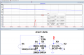
My circuit is similar to this. I use a 4N25. I have used more parts. Don't like the look of the low pulse widths. They are too wide. Mine are much narrower than these. I have found you can't pick up a rising or falling pulse on Arduino. They are too brief. But you can use pulse widths in your programming as I have suggested somewhere else on this topic.

If you are polling in software to catch these edges you will have very poor results.
The standard way to do this is by using interrupts. Certain IO pins can be configured to automatically cause an interrupt on rising or falling edges.
This way, timing jitter can be reduced dramatically, and you don't need to waste CPU bandwidth on polling.
 

Juhahoo

Joined Jun 3, 2019
302
That is the problem detecting the edge. I have found Arduino can't pick it up.
Arduino cant pick up the edge !?!?!? Zero crossing circuits ouput clear logical High or LOW. Why cant you pick it up ?!, confusing...

Aaa.. from previous post I see that your code is running but misses the edge detection!?! First, run the MCU at full speed, and use Interrupts Like mentioned by Sensacell on post #21
 
Last edited:

Thread Starter

denison

Joined Oct 13, 2018
328
If you are polling in software to catch these edges you will have very poor results.
The standard way to do this is by using interrupts. Certain IO pins can be configured to automatically cause an interrupt on rising or falling edges.
This way, timing jitter can be reduced dramatically, and you don't need to waste CPU bandwidth on polling.
My circuit is not very different from that displayed by Eric Gibbs on LTspice. I am now suddenly getting longer low pulses. They were previously 0.28ms and are now .75ms. I was using the measured pulse length to set my phase control turn on points. I think this may be due to the high mains voltage I am getting at the moment at 253v. Its usually around 240v.
How exactly do you configure an IO pin to cause an interrupt on a rising or falling edge? And you still need some kind of hardware to pick up the edge. Has anybody on the forum got a complete package to do this using Arduino?
 

Ian0

Joined Aug 7, 2020
9,667
It looks like someone else understands it.
Remember, you also have positive and negative voltage excursions, so you have to figure ou how that relates.

If your heating, "Power may not be quite right. For a resistive load, consider R a constant, so the on time table ihas phase angle and the integral (0 to PI) v(t)^2 normalized and 180-0 degrees. 180 degree firing is actually 0% or close too it.
But yea, you want % power kind of.
For a resistive load it's all V^2, so the polarity is irrelevant.
The equation calculates the energy in the load for a half-cycle, and the energy in the load for a firing angle of φ.

You can have tungsten loads (IR lamps) and you can have V loads (speed).
For voltage controlled loads, the integral is far easier! it's just a cosine.
For tungsten loads, R ∝√V so P varies as V^(3/2), but brightness doesn't vary directlty with power, because power emitted as light varies as Temperature^4 (Stefan's law), so brightness varies approximately as V^3 (if I remember correctly, it's in an Osram databook somewhere), but then, for a dimmer you want logarithm of brightness.
By the time you've worked it all out, it's not far off a straight line with firing angle for most of the transfer function, which is why a standard wall-plate dimmer doesn't do such a bad job!

Voltage compensation is a good idea as lamp_life ∝ V^(-12).
I was making lamp dimmers, so I didn't consider other types of load, and put it all in two look-up tables, one for 250V, one for 220V and interpolated depending on the mains voltage.

The normal thing is temperature control.
Unless I'm dealing with a very short thermal time constant, I'd use proportional control for heating, because it cuts down on the interference.

I do agree, that the zero cross detector isn't trivial to design. It also depends on mains frequency and that can vary a tiny bit.
So, you have that to worry about. you might have 60.1 Hz or 59.9 Hz.
Now I'm no longer in lighting I have to deal with generators. If the generator slows down, the trigger pulse is then earlier in the cycle, which gives more power to the load, which slows down the generator. If it gets the same as the generator's speed-control time constant, the whole thing can oscillate.


How to you implement Current limit? Power limit?
A fuse!

Not sure, but I think these controller use two back to back SCR's rather than a triac, so they can fire both at once to turn them off. i.e. current limit.
I've not heard about that before. I don't think you can turn off an SCR before the end of the half-cycle, unless it's a GTO.
An SCR in reverse-parallel won't conduct with its cathode at a higher voltage than its anode.
 

Ian0

Joined Aug 7, 2020
9,667
You can't operate into a transformer which we did until I said this is enough. We made30-40V tantalum heaters (evaporative sources) and the people before me used variacs to set the voltage. Our gizmos from Eurotherm had curent limit pots, so once I used 25A units with I^2*t fuses and 3AG load fuses we quit spending lots of money on semiconductor fuses. Our sources were in a vacuum chamber, so shorts were common.

Later, I said lets use a DC power supply with a 0-5V input and our problems went away. Eurotherm used transformer triggered dual SCR units and temperature controllers that controlled the SCR units directly. they moved away from that to standard process signals like 0-5V, 0-10V or 0-20mA or 4-20 mA.
 

Juhahoo

Joined Jun 3, 2019
302
How exactly do you configure an IO pin to cause an interrupt on a rising or falling edge? And you still need some kind of hardware to pick up the edge. Has anybody on the forum got a complete package to do this using Arduino?
I found it with one single Google search.
 

Ian0

Joined Aug 7, 2020
9,667
You can't operate into a transformer which we did until I said this is enough.
My application was theatre lighting, where a fuse is the usual overload protection! It's not that good as overload protection but the triacs are made so that they are easy to replace. (Like inventing rubber gloves as a cure for leaky fountain pens!)
I have not had problems driving transformers, but if they are toroids, then you must keep the trigger angles symmetric otherwise the DC offset will saturate the transformer.
An ordinary bobbin transformer which naturally has small gaps in its magnetic circuit gives you more margin for error.
As I said in a previous post, the AC input opto isolators are sometimes not as symmetric as one would might expect them to be!
 
Here's https://www.daenotes.com/electronic...off-commutation-circuits#sthash.h4WZNnBd.dpbs a collection of turn-off circuits. There is a method using a transformer on the gate.

That may have been the method they used for current limiting. The range of adjustment was 25% to100% the fuse rating.
the "SCR unit" consisted of two SCRs and an ammeter and the following inputs:

Two pairs of trigger signals
External terminals to set the current limit with a resistance.
Two terminals for Current feedback to the controller.

The PID controller was all analog and they had a potentiometer that set the "maximum output of the error amplifier"
 

Thread Starter

denison

Joined Oct 13, 2018
328
hi deni,
Use the Sensacell circuit and program the Arduino for On pin interrupt.

Do you have any Code written, if so post it and we can add the ISR.

E
https://circuitdigest.com/microcontroller-projects/arduino-interrupt-tutorial-with-examples
HI Eric, I have a simpler circuit now than the Sensacell. I have attached the circuit which I have simulated with Ltspice. It gives a maximum pulse length of only 75us.
I will try an interrupt routine to pick up the rising edge. Although I have seen from another posting that someone else could not pick up the rising edge when using a longer program in the interrupt routine.. Same as my problem with the "bool state" program.
Is it possible to slow down the running of a program so that Arduino can pick up these rising edge pulses? I will try adding a microsecond delay in my program which might do it before I try an interrupt routine.
 

Attachments

ericgibbs

Joined Jan 29, 2010
18,766
hi deni,
First observation is that the ZCD pulse and Arduino are not isolated from the mains supply and so could be a electrical safety hazard to the user.

The actual period that ZCD pulses are above the logic '1' threshold is only ~ 20uSec.

I would recommend that you reconsider and use the Sensa version, with On Pin interrupt

E
 

Attachments

Last edited:
Top