Below is the LTspice sim of a simple comparator using two PNP transistors in a differential pair, along with an NPN output driver.
PNP's are used, since they allow operation with an input voltage down to 0V with a single positive supply.
The U1 pot allows adjustment of the trigger point (Ref) voltage to 0.5V from the 5.2V supply with over a ±200mV adjustment range.
The sim shows the MOSFET gate voltage (yellow trace) going high and powering the load (red trace) when the input (green trace) reaches 497mv, with a pot setting of 50% (0.5).
I don’t know about less component solution.
Maybe those we deal with zener at beginning, but negative control voltage is needed as you can see.
Circuit in post #22:
A 10k resistor needs to be supplied from constant voltage (5.2V in your case), otherwise the comparator will not be presice.
You can use a zener for this if 5.2V source is not stable.
There is also a trick to replace 220 ohm with schottky like BAT46. In that case the supply for 10k doesn’t have to be stable. But the comparator voltage will be about 0.4V (0.6V-0.2V).
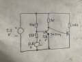
The base trigger voltage of the PNP transistor is determined by REF voltage, giving an emitter reference voltage of about 0.7V + V_REF.
When the input voltage is below the REF voltage, Q1 is conducting, since it's base voltage is below the emitter reference voltage, which turns Q5 on, giving a low voltage to M1's gate, so it is off.
When the input voltage goes above the REF voltage, then Q1 turns off, since it's base voltage is now higher than its emitter reverence voltage, which also turns off Q3, causing M1's voltage to go high, turning it on.
I don’t know about less component solution.
Maybe those we deal with zener at beginning, but negative control voltage is needed as you can see.
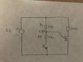
Circuit in post #22:
A 10k resistor needs to be supplied from constant voltage (5.2V in your case), otherwise the comparator will not be presice.
You can use a zener for this if 5.2V source is not stable.
There is also a trick to replace 220 ohm with schottky like BAT46. In that case the supply for 10k doesn’t have to be stable. But the comparator voltage will be about 0.4V (0.6V-0.2V).
What voltage do you want at output low, constant or variable?
If constant you can place a diode to emitter, but the base circuit has to be modified also.
What voltage do you want at output low, constant or variable?
If constant you can place a diode to emitter, but the base circuit has to be modified also.
The most easy is just make Rc from resistor divider R3:R4.
By changing the ratio between these two resistors you can set the output voltage during transistor On state whatever you want.
During transistor Off state the output is Vcc (5.2V).
The most easy is just make Rc from resistor divider R3:R4.
By changing the ratio between these two resistors you can set the output voltage during transistor On state whatever you want.
During transistor Off state the output is Vcc (5.2V).
You can do a lot with discrete transistors but one of the problems that comes up is the temperature gradient. This makes one transistor hotter than the other or other components hotter than the others after the circuit warms up, and also when it just sits there with some normal drafts. This is why serious transistor differential amplifiers are always done using a multi-transistor IC that has several matched transistors inside.
Because your tolerance is plus or minus 20 percent, you may be able to swing it but it will take some careful testing, and attention to thermal gradients. One way to help with this is to insulate the circuit with a thermal insulator like Styrofoam, then a layer of metal foil, then another layer of Styrofoam, then another layer of metal foil. The more layers the better, but four layers is probably enough. That helps to keep the component temperatures from drifting independently from one another.
The multi-transistor IC chip solution is highly recommended if you really need to do this with all transistors. They are still just transistors, just all in one case. You can also use one of the transistors as a diode if you need a diode.
I am still trying to figure out your circuit. It seems the load transistor turns on when its 0.5vdc or above based on graph you posted.
i need the load transistor off when voltage is above 0.5vdc and load transistor on when voltage is at 0.5vdc and below. How I can do this? Input voltage is dc voltage and there is no steps. The input voltage is generated between 0V to 3 vdc thru solar panel daylight. Their is no AC involved anywhere.
Theoretically you can, but low voltage zeners (without compensation) are pretty bad refferences.
For very low voltage you can use a signal diode like 1n4148 or two in series.
For voltages around 2V I preffer to use a low power Led.
 Facebook
 Google
 GitHub
 Linkedin