zener diode value

Thread Starter

hacksaw

Joined Nov 19, 2006
6
Hi all

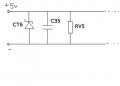
I'm trying to work out the value of a zener diode (CT6 in attached diagram) that blew when I accidentally connected the power to my mp3 player reverse polarity.

Attached is a diagram of the power-input cicuit that i buzzed out. These are the first few components near the power connector on the player that connects to the wall power pack which puts out 5v at 2A.

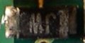
The part in question is a two leg SOD323 package with JW printed on it.
At this stage I'm looking at replacing it with a 5.6v zener diode of same package size. I'm guessing this zener is used to protect the circuit from voltage spikes.

Can anyone comment on the function of the zener diode (CT6 in diagram) and a possible value for it.

regards
James
 

Attachments

beenthere

Joined Apr 20, 2004
15,819
Hi,

I wonder if it's a zener. I would guess it would be a varistor transient surge absorber. Panasonic, Epcos,Avx, and Littlefuse all make them. You'd probably want on that operates in the 5.5 volt range. Should give better protection than a zener as they are bidirectional. They have a very high impedance until the breakover voltage is reached. While the voltage is above breakover, they almost go short. They operate fast enough to just pull voltage spikes down without blowing the circuit.
 

Thread Starter

hacksaw

Joined Nov 19, 2006
6
If so how I would a test such a device.

The mp3 player can take power from either the wall plug pack or USB from the computer, so it has two of these devices one for each power source. I have taken out the second good one from the USB source to look at it. On the diode setting on the multimeter is gives a foward voltage of 1.4v if this is any help ?
 

Thread Starter

hacksaw

Joined Nov 19, 2006
6
The part is banded which I assumed is the the cathode, and the banded side connects to the positive input hence the assumption that is is a zener(it also blew short).

I have attached a picture of it in the hope that someone may at least be able to point me in the right direction to sourcing something similar.

thanks
James
 

Attachments

Thread Starter

hacksaw

Joined Nov 19, 2006
6
hi

I have done some more tests with the multimeter on this component labled JW.
As the component is banded I will refer to that leg as the cathode(K).
The component has a capacitance of 7.6uF measured in either direction.

On the diode setting with the neg. on the cathode and pos. on the anode I get a voltage of 1.4v, 0v when the leads are reversed.

On the buzzer setting, with the neg. on the cathode it will beep once then when I take the leads off and put them on again it doesn't beep. However if I now reverse the leads it will beep once and exhibit the behavior described above. Then vice versa, also most like some kind of logic gate.

on resistance setting I can't get a definitive reading the resistance seems to change increasing or decreasing depending which way the leads are placed on, the readings are in the M ohm range.

any further help on this would be greatly appreciated.
 

richbrune

Joined Oct 28, 2005
126
I noticed that in the attached photo of the device, it appears to be soldered in. Are you performing the tests with the component in the circuit? If so you may have to take into account many variables caused by the surrounding circuit, or remove the component for test.
Rich
 

kc8ljh

Joined Nov 25, 2006
15
could it have been a regular diode to protect the mp3 player from opposite polarity - on second thought if it was for that then it could be in series. and if it is a zener then it would be for 5 volts (or the voltage required for the mp3 player) with a series resistance before the zener. also if the zener was in backwards it would be fried.
 

Johann

Joined Nov 27, 2006
190
I agree, it could just be an ordinary diode for reverse polarity protection purposes. Any general purpose diode should do the trick as a replacement. (1N4007 for instance)
 

Thread Starter

hacksaw

Joined Nov 19, 2006
6
hi all

to keep all reading this thread informed, I have put the mp3 player back together minus the blown part and have been successfully charging it with the wall charger.

thanks for everyones replys
I will pop in now and then to check for follow ups

cheers
 
Top