Zener diode Heating Problem

Thread Starter

Miracletech

Joined Nov 15, 2019
160
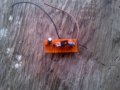
Hello everybody. I made a simple voltage regulated joule theif from HERE:
(https://upload.wikimedia.org/wikipe...oule_thief_schematic_const_voltage_de.svg.png)
Without the Zener diode, Voltage is 20volts+ but with the zener, voltage is 6v(I am using 6v2 zener). My problem here is : Why is the zener diode VERY HOT TO TOUCH?
These are the parts I am using;
3.7v dc LI-ION battery
Toroidal inductor(10 turns on primary and secondary, inductance would be 10uh each)
D882 transistor
570 ohms resistor
SR260 Fast switching diode
100uf 25v capacitor.
Any help would be greatly appreciated. Thanks.
(I feel like adding cooling paste on the Zener).
 

DickCappels

Joined Aug 21, 2008
10,153
Yes, add a resistor.

Depending upon the duty cycle of the transistor on time in your Joule thief, the circuit may be trying desperately to force the output to be more than 6.2 volts. Assuming the transistor saturates with zero volts across it (just a working assumption for the purpose of explanation) the area in the time-vs-voltage curve above 3.7 volts to the 3.7 volt level must be equal to the are below the 3.7 volt level and the waveform at ground. In other words, roughly speaking the average voltage across your primary winding needs to be zero volts over an entire cycle. That is because your primary winding has a DC resistance of nearly zero ohms.
 

DickCappels

Joined Aug 21, 2008
10,153
Sorry, I should have been more specific. Yes, put the resistor between the transformer/inductor and the Zener. You can also do the same thing by putting a resistor in series with the LED if you are using one of the circuits I am thinking of and dispense with the Zener.

1577778880087.png1577778885385.png
 

Thread Starter

Miracletech

Joined Nov 15, 2019
160
Will a 5 ohms or 10 ohms resistor give me 500MA or less? I am powering more than One 5v led to make a very brignt Night light. I am connecting them in series. Thank You very much.
 

ci139

Joined Jul 11, 2016
1,898
if your output power requirement is more than 40mA (0.04A) then your inductor size
(the cross section area of the ferrite core) needs to be bigger
1 way to achieve this is to tile several ferrite rings on top of each other
Is there any way I can connect the Zener diode to regulate the output without a current drop?
yes don't add the voltage to the output while it's not required there
-- it's simply said but that kind of DCDC converter is not too fun to be regulated
// however the link to schematic "the Scavenger" in prev. post looks . . . good , tough
// i never buy it's more than 83% efficient at moderate output load ←→ the circuit claims 5V 500mW output = 50Ω load min
// even if the converter would be 100% efficient they got 10Ω smoothing rersistor in series with the output load
// P=I·U=I(U1+U2)=P1+P2=500mW of which on 50Ω will dissipate 50/(10+60) of it = 83%
 

ci139

Joined Jul 11, 2016
1,898
http://www.ps-pfs.com/pdf/DYNATRON/D882.pdf is easy to find read documentation
assuming you use more than one 1W *led's you must pay attention to Pg.2 of the PDF to the 1-st 3-rd an the 4-th grap.-s
power against temperature // thermal resistance vs. pulse width // SOA (safe operating area -- is to be de-rated by junction temperature rize)
* -- if what you say applies (a 5V LED) then for 1W (i assume it's 1W = 2x 500mW = Nx 1/N W) it takes 200mA ←
200mA . . . sets about 300mV on CE (if driven by appropriate base current) e.g. about 60mW on D882
(without explaining) you however should use DC line from SOA graph and RΘ !!! 120C°/W ← limits your ICRMS to 625mW/300mV≈2A (??? the d/s shows 3A ???) . . . ←← this is the max RMS current through put of your D882 e.g. ::
assuming 200mΩ internal resistance for your 3.7V source E=i(r+R) → U terminal voltage @ 2A rms is about
(3.7V/2A-.2Ω)·2A=3.7-400mV=3.3V average . . . so P=IU → 3.3V·2Arms=5V·ILED , ILED.MAX.AVAIL = 1.32A (incase of no conversion losses)
the reasonable (not too optimistic) conversion efficiency is about 82% so more likely the ILED.MAX.AVAIL = 1.32A·0.82 ≈ 1.1A (← means Ldt. by D882 !)

if you want to succeed your design without too many computations use 1 led instead of many , many ferrite rings stacked or the 1W (625mW with some head room) /// i passed a mistake here . . . https://daycounter.com/Calculators/Inductor-Current-Power-Calculator.phtml gives about 2.7W for the random assumed input 3.3V , 400µH , 2A
see "Core selection by WaAc Product" pg.63 https://www.mag-inc.com/getattachme...Magnetics-Ferrite-Catalog-2017.pdf?lang=en-US
2W core (Rout x Rin x H) 9.53 x 5.59 x 7.11 - 0_40907TC , 12.7 x 7.14 x 6.35 - 0_41406TC (←about hint's the double/triple height core of the one on your pic. would do)
 
Last edited:

Thread Starter

Miracletech

Joined Nov 15, 2019
160
am only lighting one Led, like a flashlight with a switch, and please, could you Please give me the formulas above? And also, For the close loop regulation, I am using D882, 1k resistor, 5-1v zener diode, will it light the led brightly? And again, before I added the regulation, the transistor use to get a little warm, but without it, the transistor feels TOO COLD. Should it be a Problem?
 

Audioguru again

Joined Oct 21, 2019
6,673
An LED is fed a current, not a voltage like you are doing. The unlimited current you are feeding to the LED will destroy it.
You are confusing since you said a few 5V LEDs in series then later you said one high current LED that has no voltage rating.

Have you calculated the few minutes a battery charge will last when heating the Zener diode with a lot of wasted power plus lighting 500mA worth of LEDs?
 

DickCappels

Joined Aug 21, 2008
10,153
Don't worry about the transistor feeling too cold (transistors are not animate and do not have feelings). Seriously, if the transistor is saturating part of the switching time that's about the best you can hope for. Power spent heating a transistor does little or no good at room temperature.

This is not a precise circuit, so you are probably not going to find a satisfying formula for much of its operation. There is a good explanation of the way this sort of circuit works about 9 line breaks from the top of the page under "REASONING" at the following URL. https://forum.allaboutcircuits.com/threads/project-1-5v-white-led-drive.147134/

The Wikipedia entry may also prove to be of interest to you.
https://en.wikipedia.org/wiki/Joule_thief
 

Thread Starter

Miracletech

Joined Nov 15, 2019
160
I have read the wikipiedia thread about ten times, and decided to make the circuit. But anyway, I'll see what next I get. And also, I want to reduce base resistor to 56 ohms instead of 560. Any issues?(By the way, the led now lights up brighter:)Thanks for the help. )
 

DickCappels

Joined Aug 21, 2008
10,153
I'm glad you studied up ahead of time!

Changing the base resistor to 56 ohms would cause the average base current to be about 50 ma. Yes, that is probably a problem.

I take it you used this schematic:
1577862254351.png

Notice the DC path between the battery and the LED contains noting to limit the current except the current vs voltage curve of the LED. If you have a good LED it would get very hot before it ran the battery voltage down very much. That's because good LEDs tend to require less voltage. Your battery voltage is too high for some kinds single LEDs (or several in parallel, not series.)
 
Top