Facebook
 Google
 GitHub
 Linkedin
Hi,
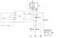
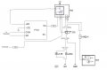
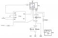
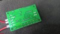
I'm trying to get this YYI-2 current sensing relay module to react to the current going towards my car's alarm siren. This should allow it to emulate the SOS-button of a car gps tracker so I can get a text message when the alarm goes off.
I tried hooking it up now, with the cable (that goes to the siren) I want to measure the current of routed through the load ports, so basically the current comes in on load+, and then it should go out on load- and supply the siren as usual. I realized that the load- port is connected internally to the DC- port (I measured continuity as well), which makes no sense to me. I connected 12V to DC+ and ground to DC-. This means there'll be a short to ground instead of having the current go through load+ to load- and then onwards to the load... How does this make any sense?
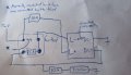
I've attached a drawing of how I've connected it, apart from the SOS button cables for simplicity. I've used a fuse thief (like this one: https://cdn11.bigcommerce.com/s-ewn...0121/WSC-83227_Main__51670.1681375811.png?c=2) that allows me to tap into the fuse slot of the siren's fuse, reroute instead through the load ports of the YYI-2 and then back to the fuse slot, so I would be able to measure the current to it, and at the same time, the thief then distributes it not only into the fuse slot that leads to the siren, but also to its second fuse slot where I've put the 7.5A fuse and it then goes out through the cable and is used to provide the tracker and YYI-2 module (in its DC+ port) with 12V.
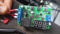
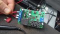
When I tried hooking it up, one of the fuses, I think it was the 7.5A one in the fuse thief, blew immediately. The YYI-2 screen was on though, and I could set my thresholds and everything. Also, the load ports are not a bypass - there seems to be a complete voltage drop, which is not surprising since the load- and DC- are connected.
There's been a previous thread about this module, and he never got it to work: https://forum.allaboutcircuits.com/...ith-relay-not-reading-correct-current.169102/
Thanks in advance!
I'm trying to get this YYI-2 current sensing relay module to react to the current going towards my car's alarm siren. This should allow it to emulate the SOS-button of a car gps tracker so I can get a text message when the alarm goes off.
I tried hooking it up now, with the cable (that goes to the siren) I want to measure the current of routed through the load ports, so basically the current comes in on load+, and then it should go out on load- and supply the siren as usual. I realized that the load- port is connected internally to the DC- port (I measured continuity as well), which makes no sense to me. I connected 12V to DC+ and ground to DC-. This means there'll be a short to ground instead of having the current go through load+ to load- and then onwards to the load... How does this make any sense?
I've attached a drawing of how I've connected it, apart from the SOS button cables for simplicity. I've used a fuse thief (like this one: https://cdn11.bigcommerce.com/s-ewn...0121/WSC-83227_Main__51670.1681375811.png?c=2) that allows me to tap into the fuse slot of the siren's fuse, reroute instead through the load ports of the YYI-2 and then back to the fuse slot, so I would be able to measure the current to it, and at the same time, the thief then distributes it not only into the fuse slot that leads to the siren, but also to its second fuse slot where I've put the 7.5A fuse and it then goes out through the cable and is used to provide the tracker and YYI-2 module (in its DC+ port) with 12V.
When I tried hooking it up, one of the fuses, I think it was the 7.5A one in the fuse thief, blew immediately. The YYI-2 screen was on though, and I could set my thresholds and everything. Also, the load ports are not a bypass - there seems to be a complete voltage drop, which is not surprising since the load- and DC- are connected.
There's been a previous thread about this module, and he never got it to work: https://forum.allaboutcircuits.com/...ith-relay-not-reading-correct-current.169102/
Thanks in advance!
Attachments
-
 2.8 MB Views: 9
 -
 2.9 MB Views: 9
 -
 3.3 MB Views: 12
 -
 612.9 KB Views: 12