Yamaha PSS-560 no sound problem

Thread Starter

YMHP95B

Joined Sep 1, 2020
5
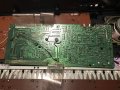
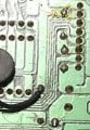
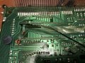
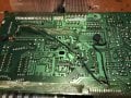
Hi. I'm trying to repair Yamaha PSS-560 keyboard that has no sound. I have the service manual. The lights come on, power is there. Tried probing for sound at the amplifier chips IC16 and IC19 with no luck. I noticed some black wires going from main IC1 chip but they aren't called on the page 13 wiring diagram in the manual. What do you think? What else should I try to see which part isn't giving sound? Thanks
 

Attachments

Thread Starter

YMHP95B

Joined Sep 1, 2020
5
Hi Joe. I have a volt meter and some alligator clips i attached to a boombox to probe for sound at various chip outputs.
 

Thread Starter

YMHP95B

Joined Sep 1, 2020
5
In my pictures you can see black wires jumping from IC1 to some other points. IC1 the main chip also has some capacitors added to jump pins across. I don't think that's factory work. I think someone has added those, i don't see them on the service manual diagram.
 

JoeJester

Joined Apr 26, 2005
4,390
So you never see it work?

With your dmm, check the voltages at the power source..... both 5 volts and the 9 volts.

This boombox .... are the jumpers going directly to the speakers without going through an amp? do you have a capacitor in series with the hot side o the cable ...... when you probe??

I would suggest you use a cheap dollar store earbuds ..... that way if you destroy them .... your only out a buck.

Anyway .... you can set the synthesizer to something .... then you can trace the sound from the output of the DAC to the input of the power amplifier.

Whatever voltage measurements you make ... take copious notes so you can report them.

What is the model of your meter?
 

JoeJester

Joined Apr 26, 2005
4,390
Ok I looked at your picture.

I'm going to assume your not the original owner and possibly not the first person to attempt a repair.

The black wires look like they are establishing the ground at those locations. The workmanship looks pretty bad and there look like solder bridges near those two capacitors. The second pin near the black wire connection looks bad, and it appears the black wire itself might not have a proper connection. You will need to confirm those pins on the schematic.

The middle black wire .... if you go up a little to where it turns 90 degrees to the right, it looks like the foil has a crack in it, with a poor attempt to renew it.

Finally near the bottom of that pic, the soldering job looks poorly dressed, lots of solder. and to the right of that on the bottom trace, there is a blob of solder that may have been an attempt to fix a crack in that trace. you can see what appears to be a wire sticking out the left side of it.

So, you need to see what those wires connect. They look OLD ... so, who knows. The schematic may have not been updated nor an errata sheet provided.

Try to use no flash and indirect light when you take pictures.
 

Attachments

JoeJester

Joined Apr 26, 2005
4,390
All that wiring was added sometime. No, it is NOT on the schemtic, but if you look at the figure of the foil side of the board .... you can trace each of those modifications to a jumper. Other than the capacitors those black wires represent ground.

IF you want to REPAIR it....and that means making sure all the black wiring is removed and you find and bridge the foil wherever there is a crack. This will take time and patience.

Those capacitors need to be looked at a little closer. They may have been added because of a previous problem.

Should you choose to remove those black wires, all you would need is a soldering iron, wire to bridge, solder, a DMM, and that foil side picture. I converted it to a jpg.

foil-side-.jpg
 

Thread Starter

YMHP95B

Joined Sep 1, 2020
5
Hi Joe, just wanted to thank you for all the suggestions you'd given me. I had a tragedy in my family so haven't been able to get to this project, but will be back at is soon. Just wanted to thank you again for the time you took to help me Joe! Sincerest thanks.
 
Top