 Facebook
 Google
 GitHub
 Linkedin
Hi,
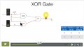
I am working on this XOR gate :

Here is what I did (before adding the OR) :
Why my LEDs still ON?

They still receive 4mA, but aren’t they suppose to receive 0mA because of the 2 NOTs on left?
Thank you in advance
I am working on this XOR gate :
Here is what I did (before adding the OR) :
Why my LEDs still ON?
They still receive 4mA, but aren’t they suppose to receive 0mA because of the 2 NOTs on left?
Thank you in advance
Attachments
-
 197 KB Views: 1
 -
 237.9 KB Views: 1
 Here is the good part :


