Facebook
 Google
 GitHub
 Linkedin
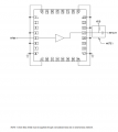
Hello,I have bought a PCB of an amplifier. The amplifier is like a lego.The problem with this is how do I bias it. I have rf_in rf_out But I dont know how to bias such things. What component do we use to deliver the DC into this amplifier component?
Is there some examples? Thanks.
https://www.analog.com/en/resources...o-prototype-rf-designs-using-x-microwave.html
https://catalog.quanticxmw.com/item/x-mwblocks/amplifiers/XM-A9V6-0604D
Is there some examples? Thanks.
https://www.analog.com/en/resources...o-prototype-rf-designs-using-x-microwave.html
https://catalog.quanticxmw.com/item/x-mwblocks/amplifiers/XM-A9V6-0604D