Facebook
 Google
 GitHub
 Linkedin
Dear All ;
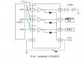
I am trying t make LED project with 6 LEDs and WS2811 LED driving IC and Darlington npn transistors as shown in the first image , but now i need to convert this npn transistors into 1 IC ULN2001D Darlington Array IC , All info attached
please notice that , WS2811 is current sink output 18.5 mA


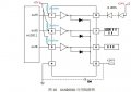
I am trying t make LED project with 6 LEDs and WS2811 LED driving IC and Darlington npn transistors as shown in the first image , but now i need to convert this npn transistors into 1 IC ULN2001D Darlington Array IC , All info attached
please notice that , WS2811 is current sink output 18.5 mA
Attachments
-
767 KB Views: 11
-
315.7 KB Views: 13
Last edited by a moderator: