 Facebook
 Google
 GitHub
 Linkedin
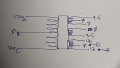
Hi folks. I'm trying to wire the primaries of the attached transformer. My mains are 120V. Currently I've only connected A and B to my mains and don't think I'm getting enough juice out of D and E, which is what I'm using for my output. Can I connect A and C together to, say, hot and B to neutral? Would that double the output of my transformer?
I saw the thread at https://forum.allaboutcircuits.com/threads/wiring-primary-of-this-transformer.56180/ and I don't think it quite answers my question, since that transformer appears to have two separate primaries, although in practice, once the two are connected in parallel it would resemble my setup.
Thanks,
Doobster.
Attachments
-
 68 KB Views: 29


