Wiring up a LED to show when a relay is closed.

Thread Starter

Niceyace

Joined Jul 24, 2024
2
Hi,

This is my first posting, so I'm hoping someone can point me in the right direction.

I'm building a demo case to show how some building automation products can work together in a smart home and act as a test bed for proof of concept work. I want to wire up some output relays that will activate a connected device when a specific digital input (a momentary switch) is thrown. This is fine, but I'd also like to include an LED to indicate that the relay has closed, even when there's no device connected.

The issue is that the relay could switch 12v, 24v, or 240v, depending on the device connected, so the indicator 3V LED would have to have an appropriate resistor added so as not to blow. If the voltage was fixed, then I can work this out, but can anyone out there think of a way to wire this up so the input voltage flowing through the relay can vary, but the LED indicating the relay is closed can still operate?

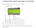
I've attached a wiring diagram that might explain this better. The output relays are inside this mini-server device. What this doesn't show is how I can incorporate an LED indicator.

Hope this make sense.
In anticipation

Dave C
 

Attachments

ElectricSpidey

Joined Dec 2, 2017
3,312
Just wire the LED in parallel with the relay coil, with the dropping resistor of course.

Ok, never mind I see the relay coils are not accessible.
 

Tonyr1084

Joined Sep 24, 2015
9,744
Welcome to AAC.

Couple questions:
The issue is that the relay could switch 12v, 24v, or 240v
Question 1) Is this AC or DC? It's important. Especially if you're switching 240V. Likely 240 is going to be AC, but it's even more important to ask IF it's DC.
Q2) What voltage are the relays activated at? Not the devices they're switching, the coil itself.
Q3) Are the relays DPDT or SPDT. OR are they SPST. There are so many configurations possible I'm not going to name them all.
Q4) IF they are DP (Double Pole) you can use the second half of the poles to switch on an LED.
Q5) What voltage are you planning on using as a power source for the LED's?
Q6) What TYPE of LED's are they? What are their forward voltages and what are the max recommended current?

LED's are current devices, not voltage. If you have a 12 VDC source and an LED with a 3.0Vf (forward voltage) and a recommended MAX current of 20mA (0.02A) you'd need a 470Ω half watt resistor. So the questions asked are important for us to be able to answer your question with reasonable confidence we're giving you the right answers.
 

Tonyr1084

Joined Sep 24, 2015
9,744
Just wire the LED in parallel with the relay coil, with the dropping resistor of course.
If the relays are triggered by a momentary push button then the LED will only be lit when the button is pressed. As soon as it's released the LED would go out. As for it being non-accessible, which I'm not seeing in the question, the LED can be wired at the switch. But again, if it's a momentary switch then it wouldn't indicate an active circuit.
 

Tonyr1084

Joined Sep 24, 2015
9,744
I can't help but feel the need to explain a little about relays and how they work. I'm not assuming you know nothing, I'm just covering the necessary bases to be sure you're headed in the right direction and that we are all discussing things from a common point of reference.

A relay has a magnetic coil that is energized by a specific voltage. In the case of your project it looks like you'd need a relay coil rated at 24V. Again, AC or DC, depends on what you're working with. When you energize that 24V coil it pulls an armature down. That armature is an electrical switch that may be rated for 240VAC or 24VDC. Again, AC or DC is important to know best how to answer your question. When that armature closes (goes into the active state) current on the coil holds the switch active. When energy is removed from the coil the switch will open up.

You're use of a push button (PB) doesn't easily lend itself to lighting an LED and having that LED remain lit. Not unless the relay is self locking. OR if you use a settable / resettable relay. I won't get into that because I don't want to confuse things.

In short, a low voltage, low current can control a much higher voltage or current device, depending on the switch rating.
 

Thread Starter

Niceyace

Joined Jul 24, 2024
2
Many thanks for the feedback, and I appreciate some further information is needed here.

So we're a reseller of LOXONE, a building management and home automation system, based around a hardware product call the Miniserver. I've attached the product datasheet.

Putting aside the analogue inputs, this device has eight digital inputs (24VDC) and eight digital outputs (max 250VAC/10A - max 30VDC/10A). Through the Miniserver configuration, any specific input can control any combination of devices connected to any of the outputs.

Loxone provide a democase (@£1000) which has momentary toggle switches connected to the eight digital inputs, to simulate a digital device triggering an event. The outputs are simply connected to an LED, to indicate when the associated output relay is closed. I've attached a screenshot of a democase with the miniserver and associated momentary switches and output LEDs shown. To the left of the output LEDs, you'll see three green connection blocks, these are the type of connection block I'd like to wire into each digital output, to enable an external device to be connected to the PCB.

I wanted to take this one step further and create a PCB with both the LED indicator as well as a block connector, to which we could connect an actual device. I may have taken this too far in stating that the output voltage could be variable, 12VDC, 24VDC, 240VAC, but I was thinking this would accommodate multiple scenarios.

Hope this provides a better picture of what I'd ideally like to achieve.

Dave C
 

Attachments

MisterBill2

Joined Jan 23, 2018
27,159
After looking at the specifications it seems to me that the designers really should have looked at the "Automation Direct" catalog to understand what a controller should provide. Even cheap PLCs include indicators for inputs and outputs as part of the device.
A small PCB that has connections for the digital outputs and could connect to the spring terminals wold certainly be possible. But it would need to use flexible wire connections because releasing multiple spring terminals in unison would be a serious challenge.
 

crutschow

Joined Mar 14, 2008
38,316
Below is the LTspice sim of a constant-current circuit that keeps the LED current relatively constant from 12Vdc to 240Vac:
Points A and B would be the output of relay to the power common.
It uses a high-voltage MOSFET to keep the LED current (bottom trace) at around 2mA, which should give sufficient brightness from a high-brightness type LED.
2mA keeps the maximum MOSFET power dissipation to <0.5W.

1722106079220.png
 
Last edited:

MisterBill2

Joined Jan 23, 2018
27,159
OK, and now, finally I think that I get it. Your panel will provide the indications WHILE IT IS ACTUALLY CONTROLLING SOMETHING, rather than just standing alone. Like an actual PLC would do. So how to indicate that the unit has switched a load. The simple way would be to create a set of one-channel PCBs that would include supply terminals and load terminals, and also a pilot light for one of the three voltages. That would allow mix and match with no switching, just select the correct board for each contact/voltage supply. That could become a standard accessory product for your company to sell. Using different colored indicators would stress even more that different voltages could easily be handled. A different color of paint for each voltage would demonstrate the flexibility even more..
 

boostbuck

Joined Oct 5, 2017
1,032
Since it's a one-off demo unit, you could use the relay contacts within the server to switch a 24VDC relay on a separate board, using the 24VDC supply. This outboard relay could have a LED in parallel with it, since the driving voltage is fixed at 24VDC, and it's contacts become the contacts that switch the load.
 

MisterBill2

Joined Jan 23, 2018
27,159
My impression is that the TS wants to be able to demonstrate the device operating actual loads with it's internal relays, rather than an external buffer relay. THAT would very much give the wrong impression.

And now I am wondering if it is possible to open that demo unit and wire in some LEDs that could then be mounted into the case wall near the output terminals. An interesting modification.
AND I suggest that the TS investigate the pricing of similar PLCs. I suspect that one with similar capabilities would be much less expensive from "Automation Direct". But programming in ladder logic instead of home-automation code may be a show stopper.
 

Externet

Joined Nov 29, 2005
2,624
I would connect the LED indicator in parallel to the relay contact. Negative logic: Light off means contact is conducting. Tapping the 'coil' tells the coil is energized, not that the contact is closed.
If that LED will be exposed to many voltages by the same relay open contact; rectifying and limiting current is to be handled for the LED, optoisolating or not can invert the logic also.
 

MisterBill2

Joined Jan 23, 2018
27,159
I would connect the LED indicator in parallel to the relay contact. Negative logic: Light off means contact is conducting. Tapping the 'coil' tells the coil is energized, not that the contact is closed.
If that LED will be exposed to many voltages by the same relay open contact; rectifying and limiting current is to be handled for the LED, optoisolating or not can invert the logic also.
That would not last long when using it for 220 volts AC. Also, negative logic can be confusing to those not aware of it.
Also, it is very difficult to tell the difference between ZERO and NOTHING. like when the power feed is off.
 
Top