wiring small vintage sew machine motor

Thread Starter

Jpols

Joined Apr 16, 2018
31
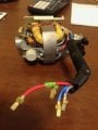
Am dealing with the motor out of a 70's era european built sewing machine. It is 110V and I believe it was two-speed but not sure. It has four wires coming from it; red ( to frame of motor), blue, grey, and black. I am trying to figure out which wires to connect to one side of power and which wire/s to connect to one side of foot control. If it is two speed, would be interested in how to wire to a switch to select speed, otherwise simply interested in high speed connections.
 

Attachments

MaxHeadRoom

Joined Jul 18, 2013
28,684
Can't quite see, does it have brushes, as most older S.M. motors were Universal motors.
If it does you can generally control the speed with the 'Dimmer' style controllers.
Max.
 

MaxHeadRoom

Joined Jul 18, 2013
28,684
Normal configuration is two leads as the armature and the field windings are in series, not sure how they connect the three, maybe do some tracing to try and see what the hook up is.
Often the foot pedal had a simple variable resistance control.
max.
 

Thread Starter

Jpols

Joined Apr 16, 2018
31
Normal configuration is two leads as the armature and the field windings are in series, not sure how they connect the three, maybe do some tracing to try and see what the hook up is.
Often the foot pedal had a simple variable resistance control.
max.
 

Thread Starter

Jpols

Joined Apr 16, 2018
31
Yes, once I can figure out which motor wires to use, I plan to complete circuit using power source interrupted with foot rheostat. Just not sure process to use to identify path through motor:) Appreciate your help!
 

MaxHeadRoom

Joined Jul 18, 2013
28,684
Look pretty cramped but if you can come up with where the wires end up, field or brushes etc, it may help, do you have a meter?
Max.
 

Thread Starter

Jpols

Joined Apr 16, 2018
31
So, I removed brushes and checked for continuity at brush holders. The grey & black wires both have continuity to the same brush holder, the blue wire has continuity to the other brush holder. Red appears to be a ground attached to frame of motor.
 

Thread Starter

Jpols

Joined Apr 16, 2018
31
Thats odd, particularly for a Universal motor, is there any clue as to the field windings ?
I will dismantle the motor (have to clean away) and see if I have a better view. Am probably doing something wrong in testing. The motor was working before I removed it from the machine. I could not follow wires at that time as they were connected to a circuit board which is not there.
 

LesJones

Joined Jan 8, 2017
4,189
I suspect that one of the field windings may be tapped. (Or that the grey or black wire connects directly to one brush holder.) It would have been more helpful if you had posted the actual resistance readings. My feeling is that blue will be connected to one leg of the supply and EITHER grey OR black to the other leg of the supply. The connection that has more turns on the field winding will give the lower speed. This is only a guess.

Les.
 

Thread Starter

Jpols

Joined Apr 16, 2018
31
thanks for your interest! Didn't have time today, but tomorrow I will post photos of the original setup & connections. Am hoping it will provide some additional insight. The four wires were connected to a small circuit board of which I don't have the expertise to identify the components. Am sure you guys will be able to help. - Jim
 

Thread Starter

Jpols

Joined Apr 16, 2018
31
Okay, here are a couple of photos showing the motor as it would have been originally hooked up. On the circuit board, the pins are numbered left to right, 1 to 9. The motor is connected to pins 2,4,5,6. Pins 1 & 3 are where the work lamp connected. The AC power/switch, connected to the board on the left to where two black wires that have been cut. On the right of the board where you can see two light blue wires that have been cut, is where the foot pedal/speed control connected. Pins 7,8,9 connected a switch that was mounted to the machine shaft and interrupted/stopped the machine ( I believe it also slowed motor too). I want to eliminate the board and simply run the motor at high speed. IMG_3912.jpgIMG_3914.jpg
 

LesJones

Joined Jan 8, 2017
4,189
I think the board is probably a phase angle speed controller. The TO220 device is probably a triac. There looks to be more components than would be required for a simple speed controller. Can you trace out a schematic of the board ?

Les.
 

shortbus

Joined Sep 30, 2009
10,045
Maybe giving the make and model number of this machine will get better answers? That way maybe a repair manual can be found, that will answer the questions.
 

Thread Starter

Jpols

Joined Apr 16, 2018
31
Okay, I took the motor apart this morning. As per attached photos, it appears brush A wire comes out of Field A (blu\blk wires), and Brush B wire comes out of Field B (Grey wire). Also, notice the blown suppressor? across the brushes, my fault when I applied power to a couple of the wires earlier. Is that a noise suppressor? Is it really needed now days? I also attached a schematic that was on the plastic board housing.
Please understand I don't really know anything about circuit boards or what the doo-dads are soldered to them are, save a resistor or suppressor.IMG_3928.jpgIMG_3926.jpgIMG_3929.jpg
 
Top